Electronic Ignition (EI) System Description and Operation
The electronic ignition (EI) system consists of the following components
and wiring circuits:
| • | The ignition control (IC) module |
| • | The powertrain control (PCM) module |
| • | The 24X crankshaft position (CKP) sensor |
| • | The camshaft position (CMP) sensor |
The EI wiring circuits listed here use service common names, they are
as follows: Between the IC module and the PCM:
| • | Low resolution engine speed signal |
Between the 7X CKP sensor and the IC module:
Between the 24X CKP sensor and the PCM:
| • | Medium resolution engine speed signal |
Between the CMP and the PCM:
The IC module also receives power and chassis ground through the following
circuits:
Purpose
The EI system is responsible for producing and controlling a high energy
secondary spark. This spark is used to ignite the compressed air/fuel mixture
at precisely the correct time to provide optimal performance, fuel economy,
and control of exhaust emissions.
Operation
In this EI system there is one coil for each pair of cylinders. Each
pair is at top dead center (TDC) at the same time, and are known as companion
cylinders. The cylinder that is at TDC of its compression stroke is called
the event cylinder. The cylinder that is at TDC of its exhaust stroke is
called the waste cylinder. When the coil is triggered both plugs fire at
the same time, completing a series circuit. Because the lower pressure inside
the waste cylinder offers very little resistance the event cylinder uses
most of the available voltage producing a very high energy spark. This is
known as waste spark ignition.
EI Component Description
The following is a list of ignition system components and their functions.
24X CKP Sensor and Interrupter Ring
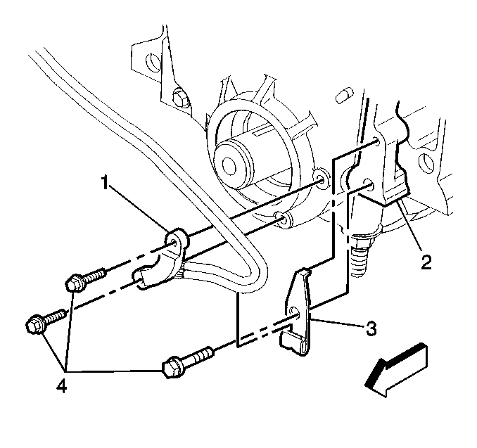
The 24X CKP sensor (1),
secured in a mounting bracket (3) and bolted to the front side of
the engine timing chain cover (2), is partially behind the crankshaft
balancer. The crankshaft balancer contains the 24X CKP sensor interrupter
ring.
The 24X CKP sensor contains a hall-effect switch. A hall-effect switch
is a solid state switching device, which produces an OFF-ON pulse when a rotating
element passes between the sensor tip and a magnet. This rotating element
is called an interrupter ring. In this case the interrupter ring has 24 evenly
spaced blades and windows. This sensor produces 24 ON-OFF signal pulses per
crankshaft revolution. The 24X signal is used for enhanced smoothness and
idle stability at a lower calibrated RPM. The 24X signal is known as the
medium resolution engine speed signal.
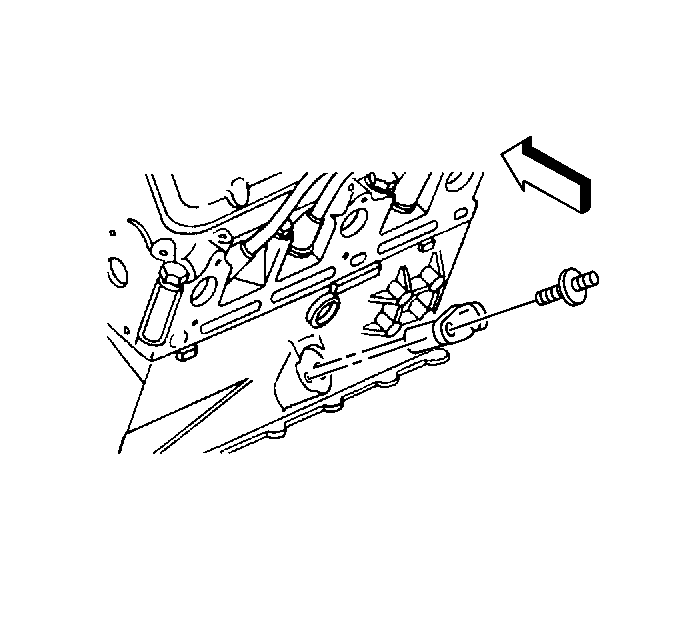
The 7X CKP sensor is bolted into the center of the engine block and
protrudes into the crankcase. The 7X CKP sensor reluctor wheel is cast into
the crankshaft.
The 7X CKP sensor is a variable reluctance sensor. The magnetic field
of the sensor is altered by a reluctor wheel that has seven machined slots,
six of which are equally spaced 60 degrees apart.
The seventh slot is spaced 10 degrees from one
of the other slots. The 7X CKP sensor produces six pulses and one
sync pulse for each revolution of the crankshaft. This signal must be present
for the IC module to send a 3X reference signal to the PCM. The 3X reference
is known as the low resolution engine speed signal.
Camshaft Position (CMP) Sensor
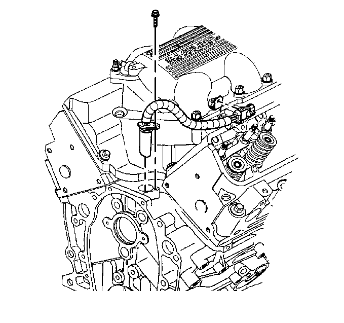
The camshaft position
(CMP) sensor is a hall effect sensor which is triggered by a magnet pressed
into the camshaft sprocket. The CMP sensor provides a signal pulse once every
camshaft revolution, known as the CMP sensor signal. The IC module uses this
signal to identify the position of the #1 cylinder at top dead center.
Ignition Coils and Ignition Control (IC) Module
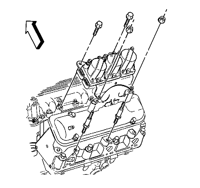
Three dual tower ignition
coils are mounted to the IC module, and are serviced individually. The IC
module performs the following functions:
| • | It receives and processes the signals from the 7X CKP
sensor. |
| • | It determines the correct coil triggering sequence, this coil
sequencing occurs at start-up, and is remembered by the IC module. After the
engine is running, the module will continue to trigger the coils in the correct
sequence. |
| • | It determines the correct direction of the crankshaft rotation,
and cuts spark and fuel delivery to prevent backfiring if this condition occurs. |
| • | It produces and sends low resolution engine speed signals to the
PCM. |
Powertrain Control (PCM) Module
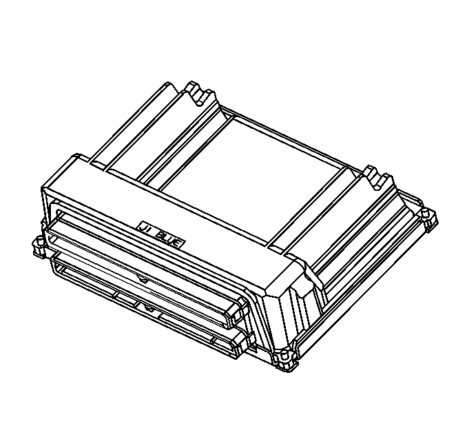
The PCM is responsible
for maintaining proper spark and fuel injection timing for all driving conditions.
Ignition control (IC) spark timing is the method the PCM uses to control
spark advance and ignition dwell. To provide optimum driveability and
emissions, the PCM monitors input signals from the following components
in calculating ignition control (IC) spark timing:
| • | Ignition control (IC) module |
| • | Engine coolant temperature (ECT) sensor |
| • | Intake air temperature (IAT) sensor |
| • | Mass air flow (MAF) sensor |
| • | Internal Mode or PNP inputs from Internal Mode switch or Park/Neutral
position switch |
| • | Throttle position (TP) sensor |
| • | Vehicle speed sensor (VSS), or transmission output speed (TOSS)
sensor |
The following describes the PCM to IC module circuits:
| • | Low resolution engine speed--PCM input--From the ignition
control module, the PCM uses this signal to calculate engine RPM and crankshaft
position. The PCM also uses the pulses on this circuit to initiate injector
operation. |
| • | Low reference--PCM input--This is a ground circuit for
the digital RPM counter inside the PCM, but the wire is connected to engine
ground only through the IC module. This circuit assures there is no ground
drop between the PCM and IC module. |
| • | IC timing signal--PCM output--The IC module controls
spark timing while the engine is cranking, this is called bypass mode. Once
the PCM receives low resolution engine speed signals from the IC module,
the PCM applies 5 volts to the IC timing signal circuit allowing
the IC module to switch spark control to PCM control. |
| • | IC timing control--PCM output--The IC output circuitry
of the PCM sends out timing signals to the IC module on this circuit. When
in the Bypass Mode, the IC module grounds these signals. When in the IC
Mode, the signals are sent to the IC module to control coil dwell and spark
timing. Proper sequencing of the ignition coils is always controlled
by the IC module. |
Ignition System Modes of Operation
Anytime the PCM does not apply 5 volts to the IC timing signal
circuit, the IC module controls ignition by triggering each coil in
the proper sequence at a pre-determined dwell. This is called Bypass Mode
ignition used during cranking and running below a certain RPM, or during
a default mode due to a system failure.
When the PCM begins receiving 24X reference and 3X reference pulses,
the PCM applies 5 volts to the IC timing signal circuit. This
signals the IC module to allow the PCM to control the dwell and spark
timing. This is IC Mode ignition. During IC Mode, the PCM compensates
for all driving conditions. If the IC mode changes due to a system fault,
it will stay in default until the ignition is cycled OFF to ON, or the fault
is no longer present.
Ignition System Service
Special care must be taken when diagnosing and handling EI systems.
The secondary voltage output can exceed 40,000 volts. Refer to the applicable
diagnosis or repair section for more information.


