GM Service Manual Online
For 1990-2009 cars only
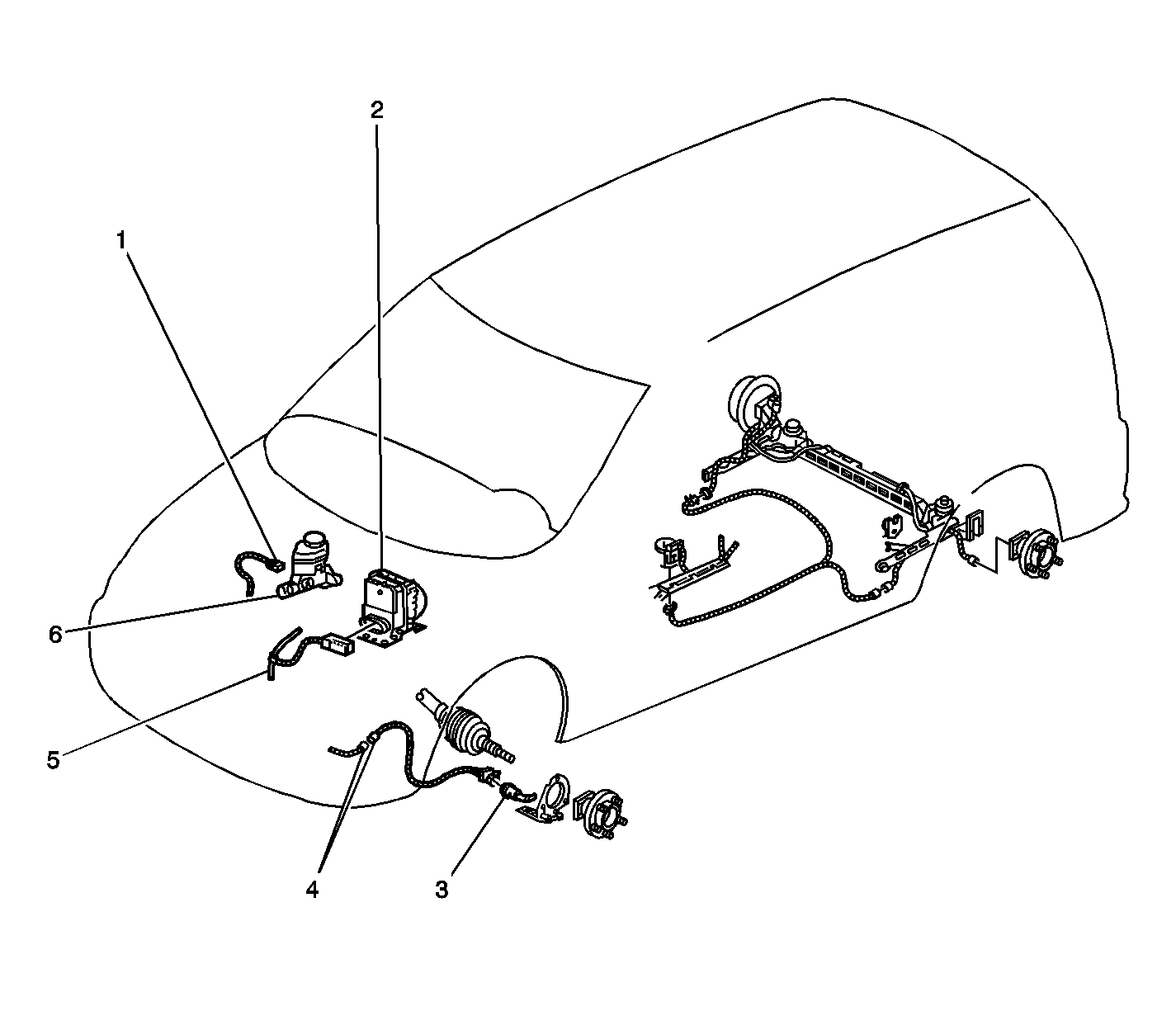
Figure 1:

Front of Vehicle


Object Number: 850759  Size: LF
(1)Brake Fluid Level Switch
(2)Electronic Brake Control Module (EBCM), Brake Pressure Modulator Valve (BPMV)
(3)Engine Harness
(4)C171
(5)Wheel Speed Sensor (WSS)
(6)Brake Master Cylinder
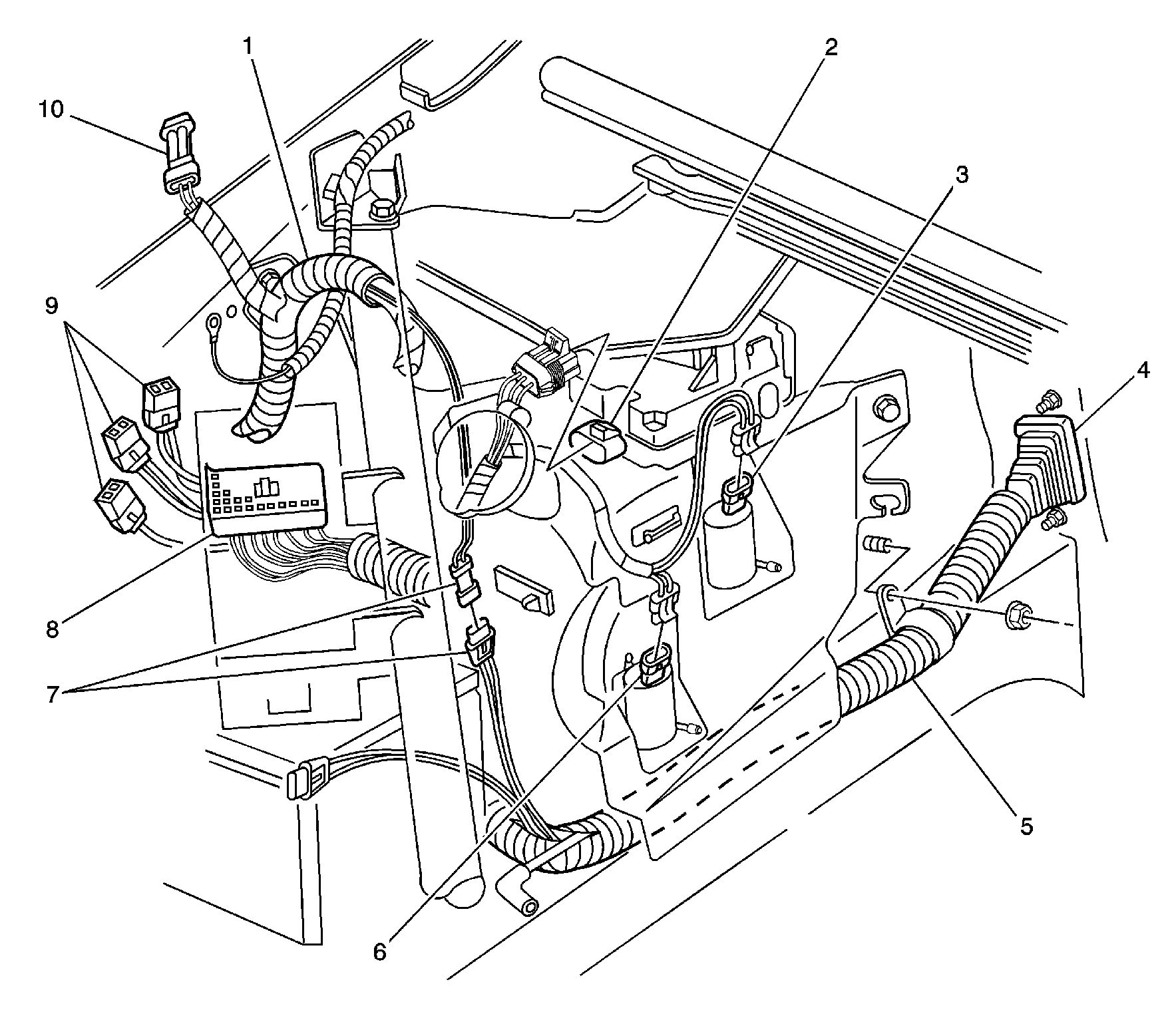
Figure 2:

Rear, Left Side of Engine Compartment


Object Number: 447050  Size: LF
(1)Forward Lamp Harness
(2)Windshield Wiper Motor
(3)Rear Windshield Washer Fluid Pump
(4)P100
(5)I/P Harness
(6)In-Line Connector C172, Engine Harness to Right Wheel Speed Sensor
(7)Windshield Washer Fluid Pump
(8)In-Line Connector C120, Engine Harness to Forward Lamp Harness
(9)Junction Block-Underhood Connector C2
(10)Junction Block-Underhood Connectors C4, C5, and C6
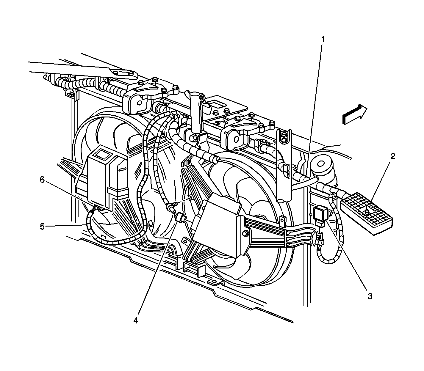
Figure 3:

Front of Engine Compartment


Object Number: 447042  Size: LF
(1)Engine Harness
(2)Accessory Wiring Junction Block-Underhood Connector C1
(3)Cooling Fan-Right Connector
(4)Cooling Fan Jumper
(5)Cooling Fan-Left Connector
(6)In-line Connector C105, Engine Harness to Cooling Fan Jumper Harness
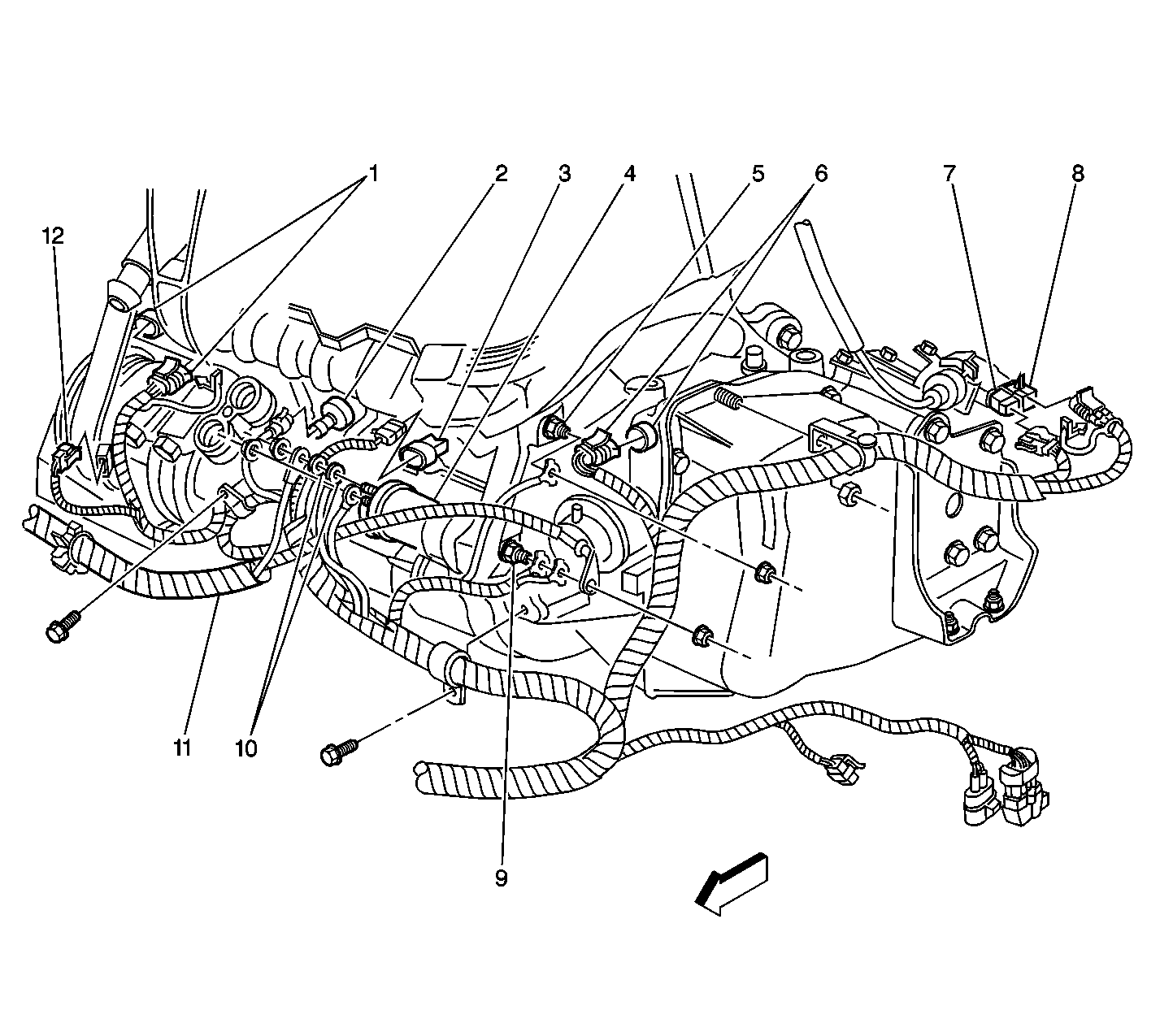
Figure 4:

Lower Front of Engine


Object Number: 478821  Size: LF
(1)Crankshaft Position (CKP) Sensor A Connector
(2)Knock Sensor (KS) Bank 1
(3)Engine Oil Pressure (EOP) Switch
(4)Starter Motor/Starter Solenoid
(5)Ground G117
(6)In-Line Connector C111, Engine Harness to Automatic Transmission Harness
(7)Transmission Range Switch Connector C2
(8)Transmission Range Switch Connector C1
(9)Grounds G111 and G113
(10)Fusible Link A and Link Z
(11)Battery Cable
(12)Engine Harness Connector to A/C Compressor Clutch
Figure 5:

Front, Right Side of Engine Compartment
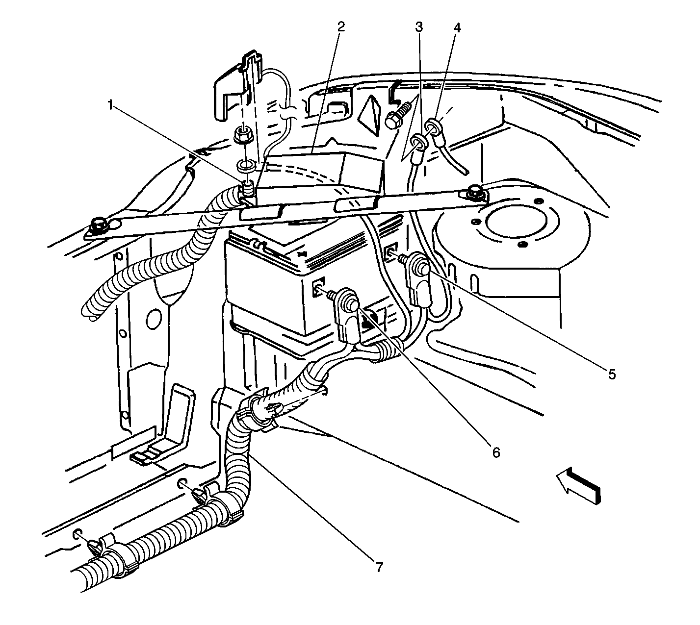

Object Number: 447114  Size: LF
(1)Remote Battery Stud
(2)Junction Block-Underhood
(3)Ground G100 (Battery Cable)
(4)Ground G102 (Forward Lamp Harness)
(5)Negative Battery Cable
(6)Positive Battery Cable
(7)Battery Harness
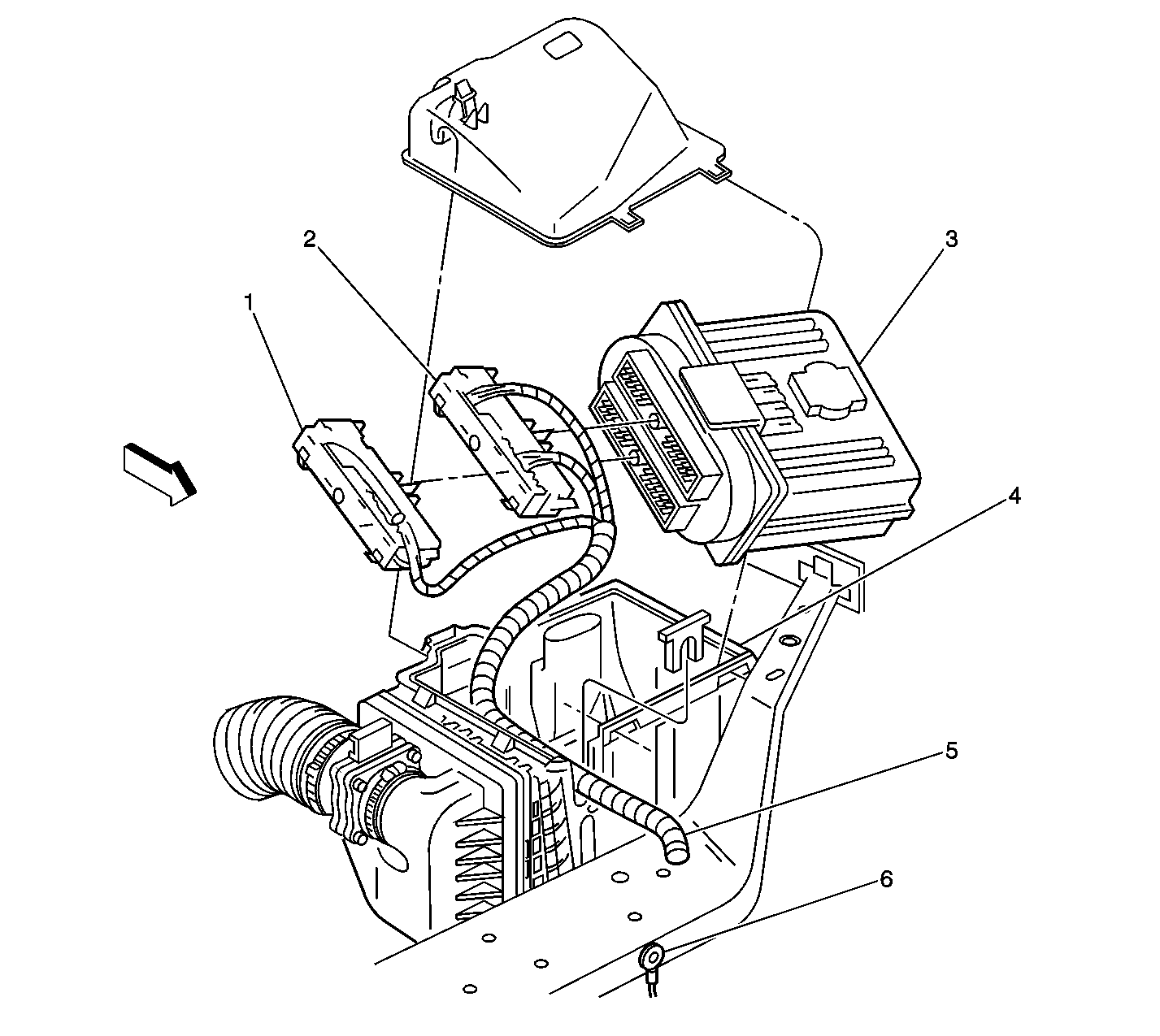
Figure 6:

LF of Engine Compartment


Object Number: 305307  Size: LF
(1)Powertrain Control Module (PCM) C1
(2)Powertrain Control Module (PCM) C2
(3)Powertrain Control Module (PCM)
(4)Air Cleaner/ PCM Housing
(5)Engine Wiring Harness
(6)Forward Lamp Ground
Figure 7:

RF Wheel (LF Wheel Speed Sensor Similar)
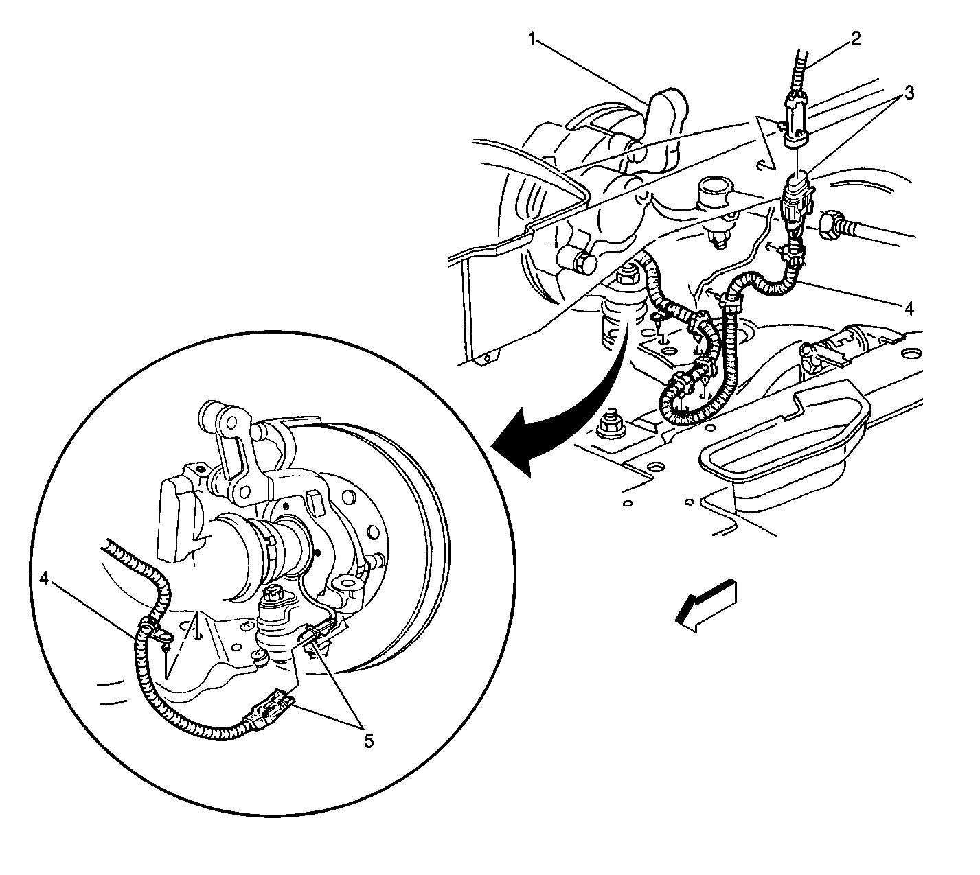

Object Number: 447321  Size: LF
(1)RF Wheel
(2)I/P Harness
(3)In-line Connector C172
(4)RF Wheel Speed Sensor Harness
(5)RF Wheel Speed Sensor Harness Connector to RF Wheel Speed Sensor (pigtail) (LF Similar)
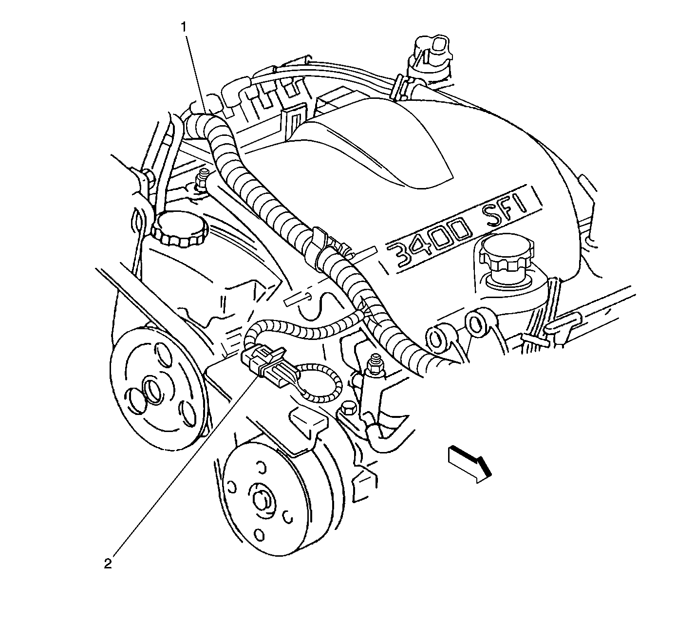
Figure 8:

Top, RH Side of Engine Compartment


Object Number: 447059  Size: LF
(1)Engine Harness
(2)Pigtail Connector to Camshaft Position (CMP) Sensor Connector
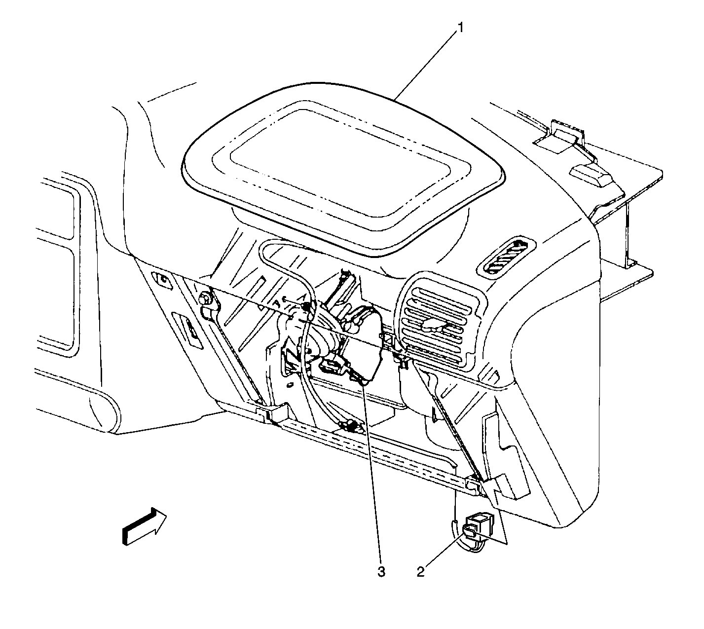
Figure 9:

RH Side of IP


Object Number: 447364  Size: LF
(1)Inflatable Restraint I/P Module
(2)In-Line Connector C216 (Yellow), from Inflatable Restraint I/P Module to Body Harness
(3)Recirculation Actuator
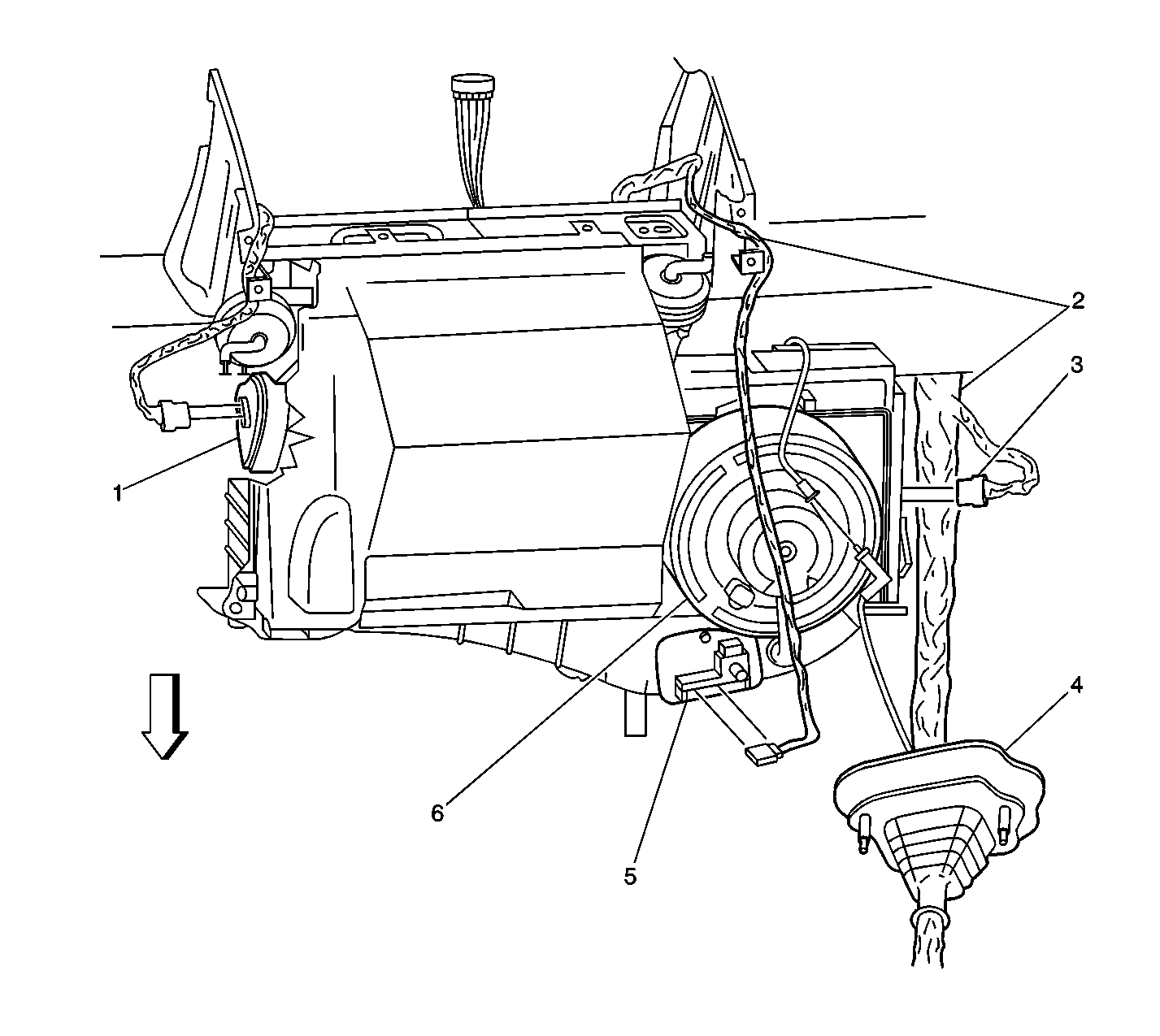
Figure 10:

RH Side of IP


Object Number: 447167  Size: LF
(1)Mode Actuator
(2)I/P Harness
(3)Connector to Recirculation Actuator
(4)Pass Through P100
(5)Blower Motor Resistor Assembly
(6)Blower Motor
Figure 11:

Below RH Side of IP


Object Number: 447202  Size: LF
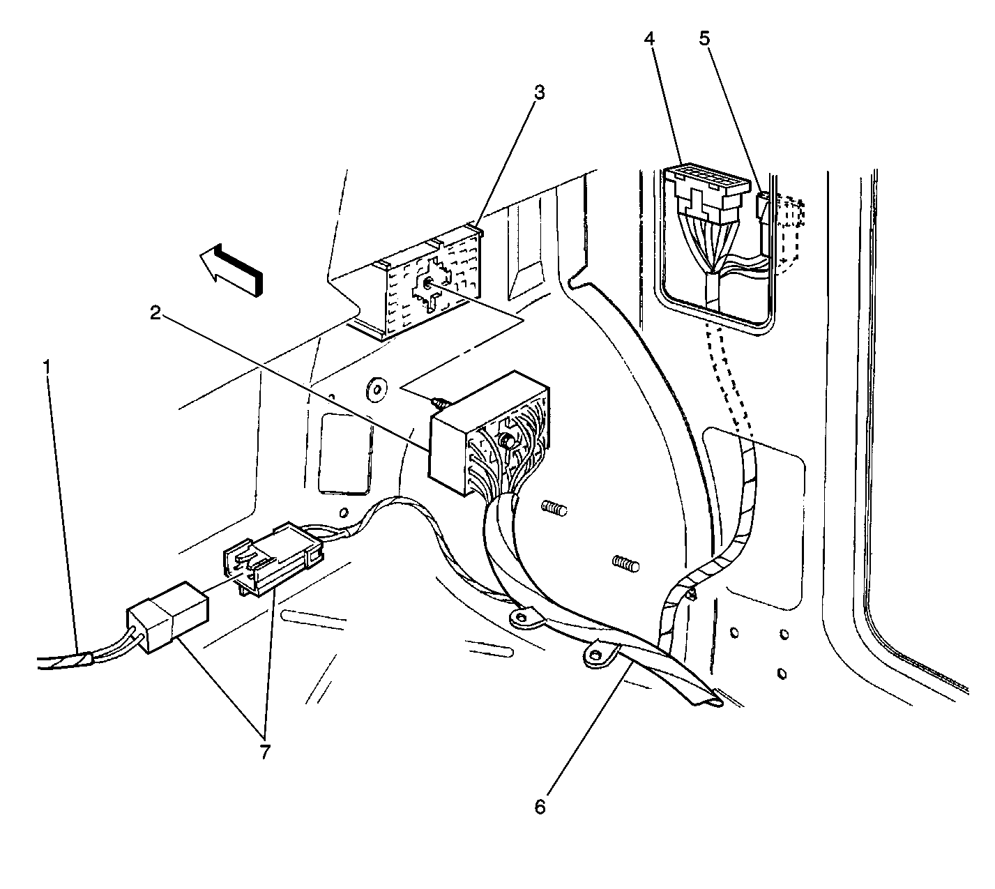
(1)Harness to Inflatable Restraint I/P Module (Yellow)
(2)In-line Connector C200 of Body Harness (C203, LH Side Similar)
(3)In-line Connector C200 of I/P Harness (C203, LH Side Similar)
(4)In-Line C302 to RH Door Harness
(5)In-Line C304 to RH Door Harness
(6)Body Harness
(7)In-Line Connector C216 (Yellow), Body Harness to Inflatable Restraint I/P Module
Figure 12:

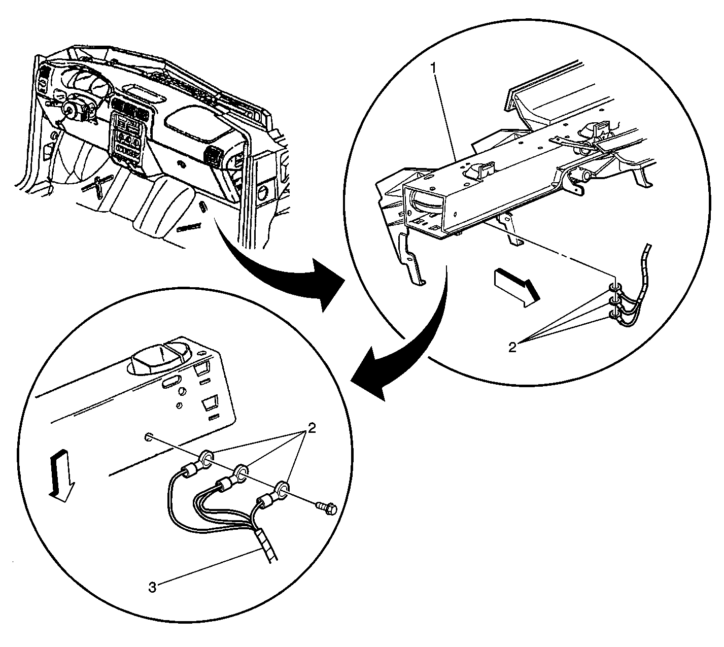
Bottom of Cross Car Beam


Object Number: 447174  Size: LF
(1)Cross Car Beam
(2)Ground G200, (G201 left hand side similar)
(3)I/P Harness
Figure 13:

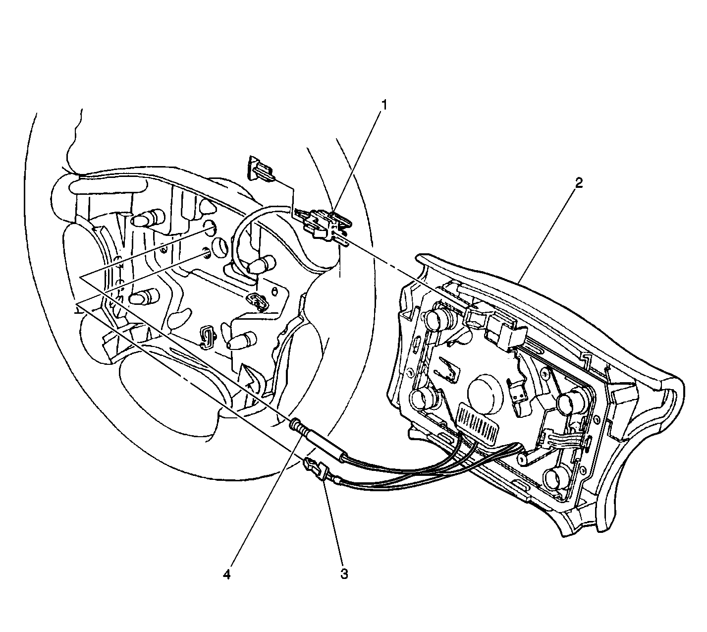
Oldsmobile Steering Wheel


Object Number: 447162  Size: LF
(1)Connector from Inflatable Restraint Steering Wheel Module Coil
(2)Inflatable Restraint Steering Wheel Module
(3)Ground from Horn Switches
(4)To Horn Switches
Figure 14:

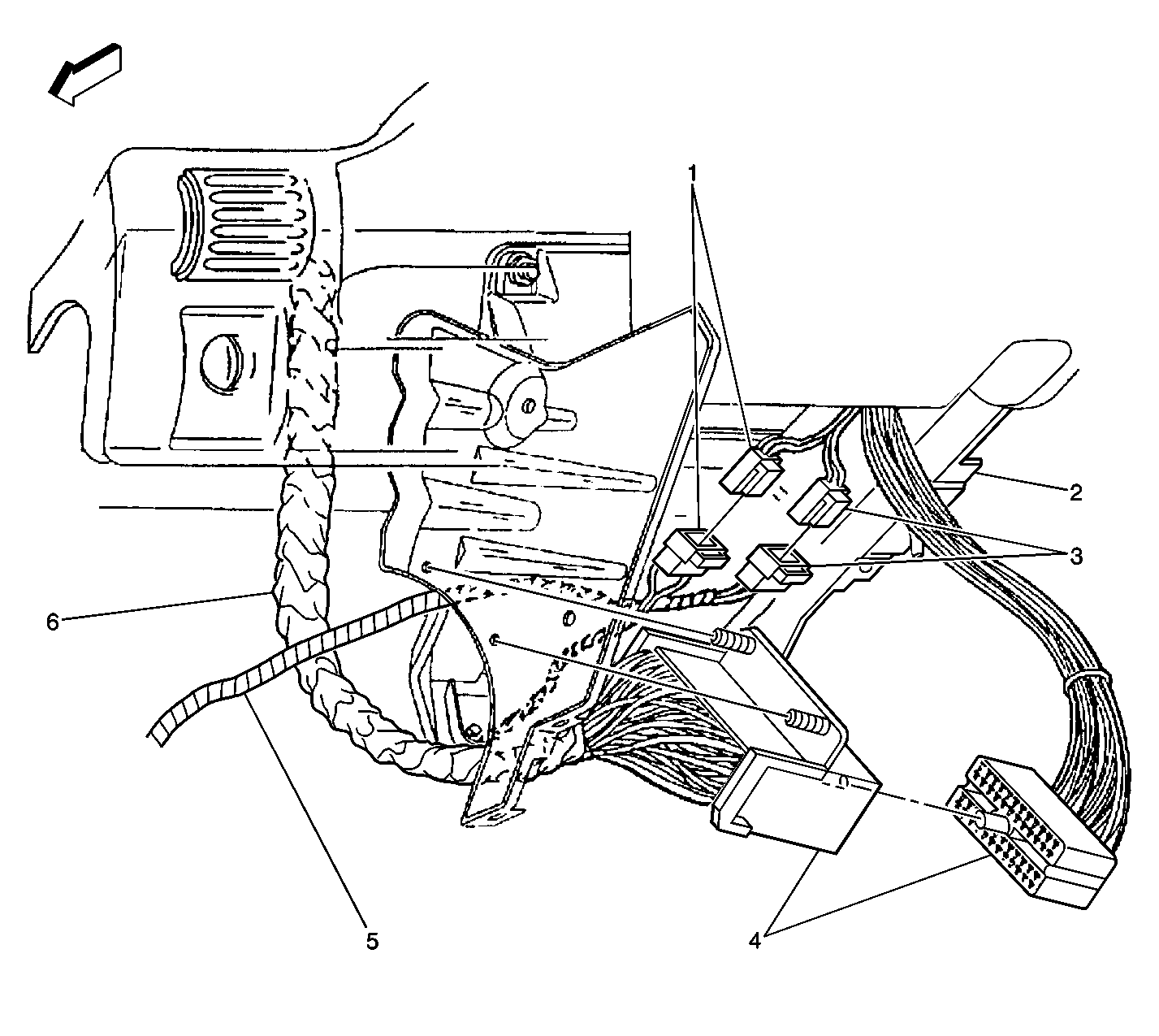
Base of Steering Column


Object Number: 447148  Size: LF
(1)In-Line Connector C205, I/P Harness to Steering Column Harness
(2)Steering Column
(3)In-Line Connector C215 (Yellow), I/P Harness to Inflatable Restraint Steering Wheel Module
(4)In-Line Connector C201, I/P Harness to Steering Column Harness
(5)SIR Harness
(6)I/P Harness
Figure 15:

Video Entertainment System Relay and Splices
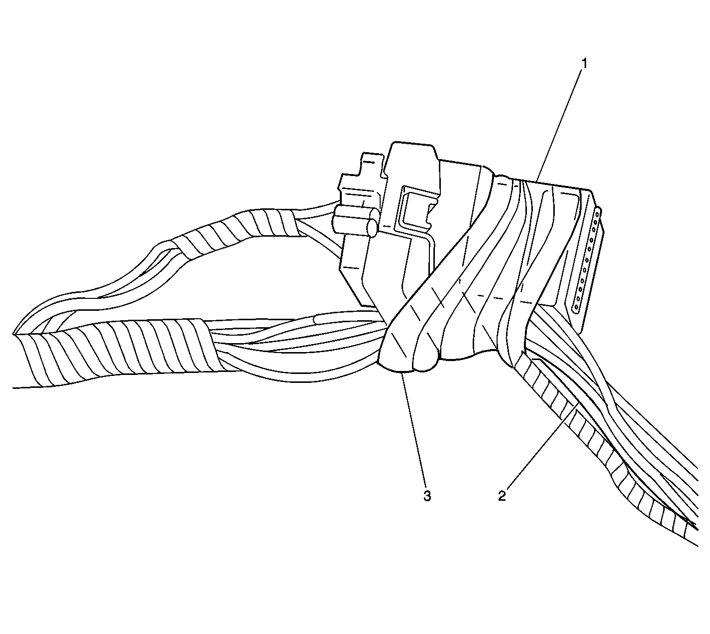

Object Number: 416766  Size: LF
(1)Video Entertainment System Relay (if equipped)
(2)S290
(3)S291
Figure 16:

Video Cassette Player (VCP), Video Entertainment System (VES) Relay, and G210
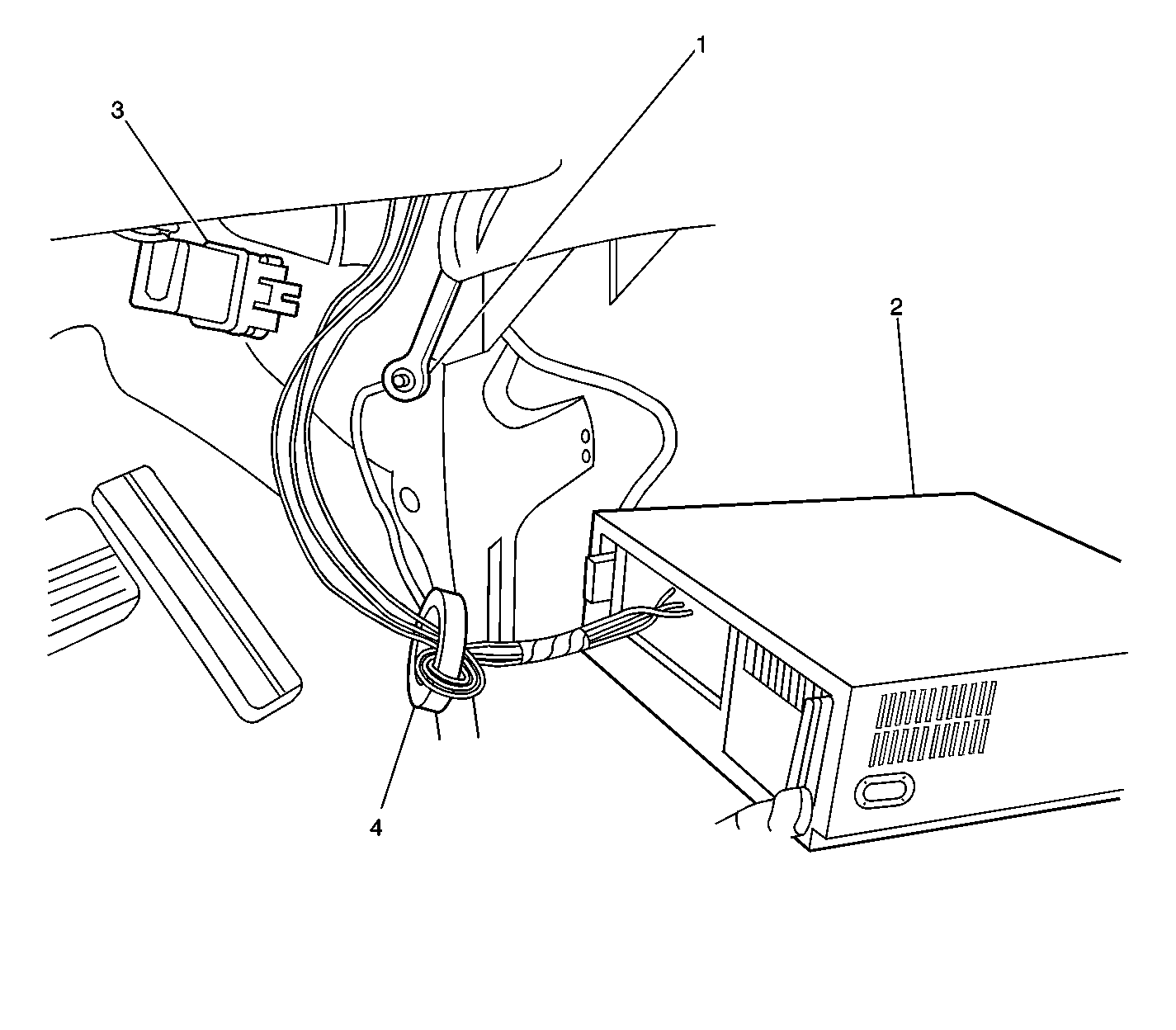

Object Number: 416756  Size: LF
(1)G210
(2)Video Cassette Player (VCP)
(3)Video Entertainment System Relay (if equipped)
(4)Noise Suppression Ring (if equipped)
Figure 17:

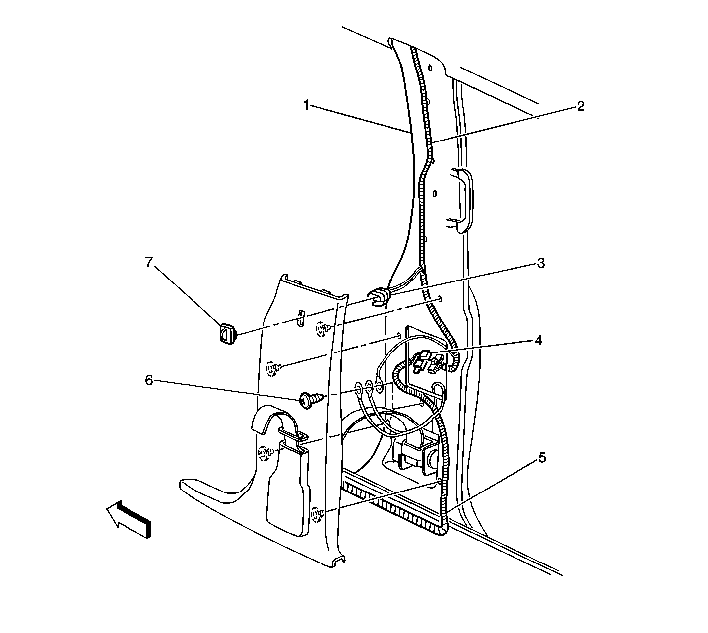
RH B-Pillar


Object Number: 447199  Size: LF
(1)RH B-Pillar
(2)Dome Lamp Harness
(3)Power Sliding Door Open/Close Switch Connector
(4)In-line Connector C308, Body to Dome Lamp Harness
(5)Body Harness
(6)Ground G302
(7)Power Sliding Door Open/Close Switch
Figure 18:

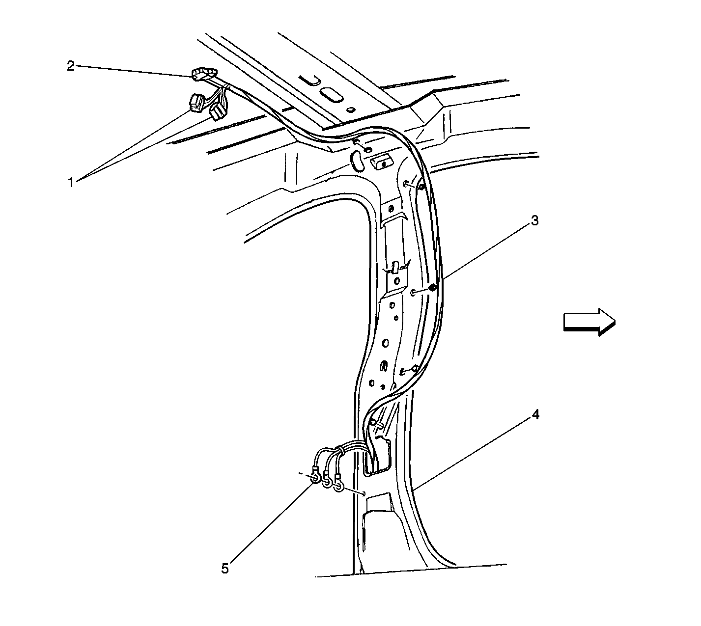
LH B-Pillar


Object Number: 447237  Size: LF
(1)HVAC Control Assembly-Auxiliary Connectors C1 and C2 or Roof Rear Console
(2)Rear Seat Audio (RSA) Control of Roof Rear Console
(3)Body Harness
(4)LH B-Pillar
(5)Ground G301
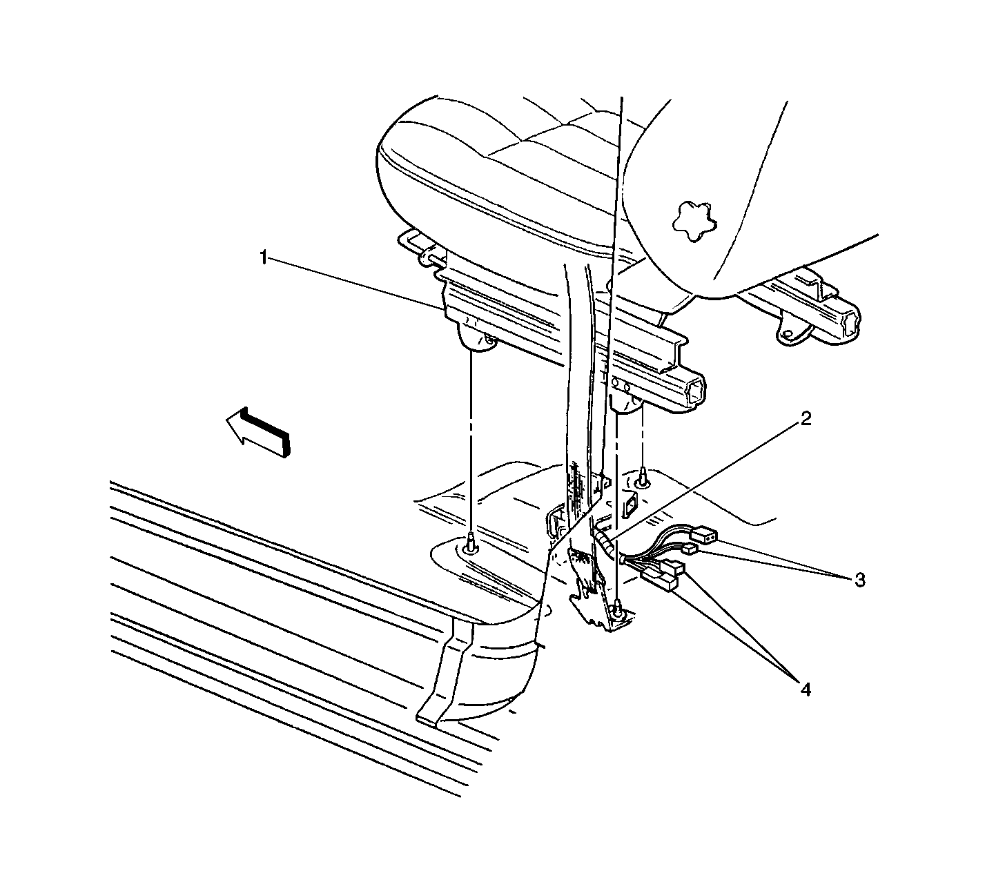
Figure 19:

Below Driver's Seat


Object Number: 447181  Size: LF
(1)Drivers Seat
(2)Body Harness
(3)Driver Seat ModuleConnectors
(4)In-line Connector C313 (C314 Similar) and Connector to Seat Belt Switch-Driver
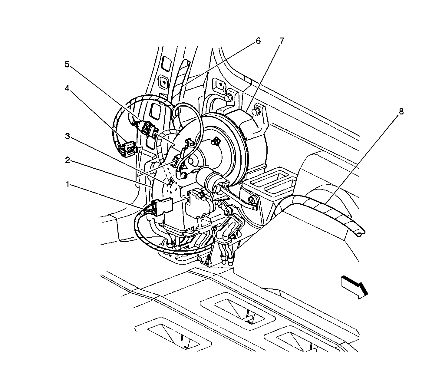
Figure 20:

Underneath Vehicle, Behind Driver's Seat
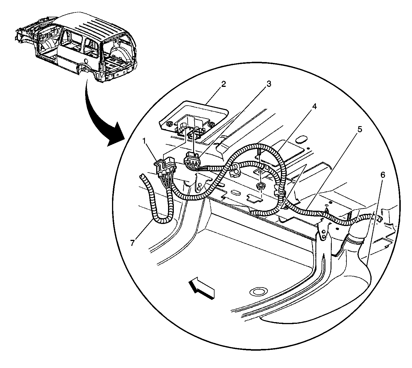

Object Number: 447318  Size: LF
(1)In-line Connector C305-Fuel Sender Harness
(2)In-line Connector C305-Body Harness
(3)In-line Connector C305-Electronic Brake Control Module (ECBM) Harness
(4)Fuel Sender Harness
(5)Electronic Brake Control Module (ECBM) Harness
(6)Fuel Tank
(7)Evaporator Emission (EVAP) Canister Vent Solenoid Valve
Figure 21:

Right Quarter Panel (Right Sliding Door Module) Left Similar
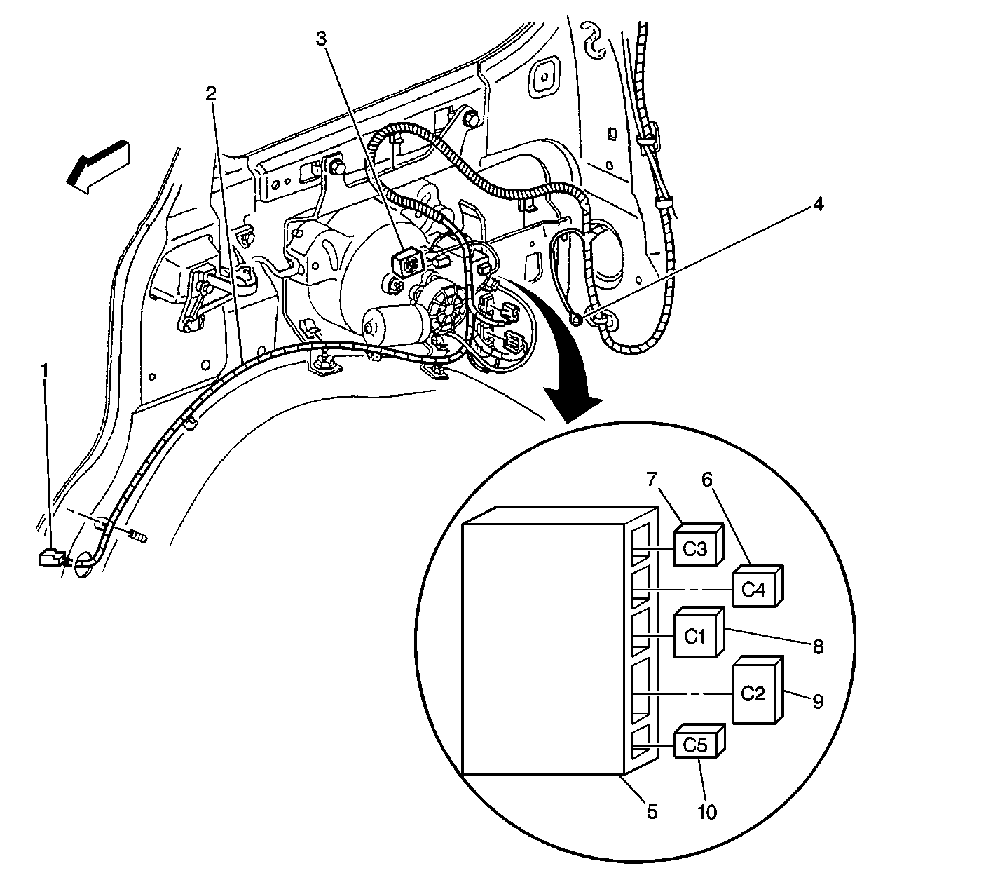

Object Number: 534488  Size: LF
(1)Sliding Door Jamb Switch-Right
(2)Body Harness
(3)Rear Sliding Door Alarm
(4)Ground G402
(5)Right Sliding Door Module
(6)Right Sliding Door Module Connector C4 to Cable Motor in Rear Side Door Actuator Motor
(7)Right Sliding Door Module Connector C3 to Clutch in Rear Side Door Actuator Motor
(8)Right Sliding Door Module Connector C1
(9)Right Sliding Door Module Connector C2
(10)Optical Sensor Harness from Right Sliding Door Module Connector C5 to Optical Sensor in Rear Side Door Actuator Motor
Figure 22:

Behind Rear Left Wheelhouse


Object Number: 447341  Size: LF
(1)Connector to Air Temperature Actuator-Auxiliary
(2)Ground 401, Secured to Lower LH D-Pillar
(3)C405 (Inset)
(4)Connector to Auxiliary Assembly-Blower Motor Resistor
(5)Connector to Auxiliary Assembly-Blower Motor
(6)Body Harness
(7)HVAC Control Assembly-Auxiliary
(8)Body Harness
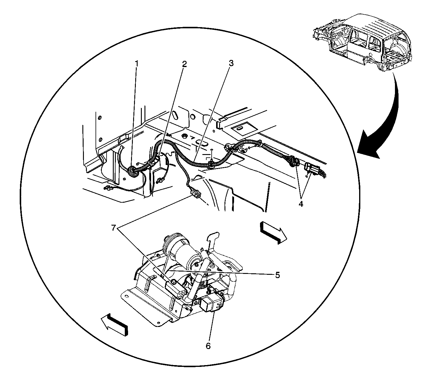
Figure 23:

Below Vehicle, Rear of LR Wheelhouse


Object Number: 447384  Size: LF
(1)Pass Through P403
(2)In-line Connector C407
(3)Automatic Level Control (ALC) Harness
(4)Automatic Level Control (ALC) Sensor Connector
(5)Automatic Level Control (ALC) Air Compressor
(6)Automatic Level Control (ALC) Air Inflator Relay
(7)Automatic Level Control (ALC) Connector
Figure 24:

Video Cassette Player (VCP), Video Entertainment System Relay, and G210


Object Number: 416756  Size: LF
(1)G210
(2)Video Cassette Player (VCP)
(3)Video Entertainment System Relay (if equipped)
(4)Noise Suppression Ring (if equipped)
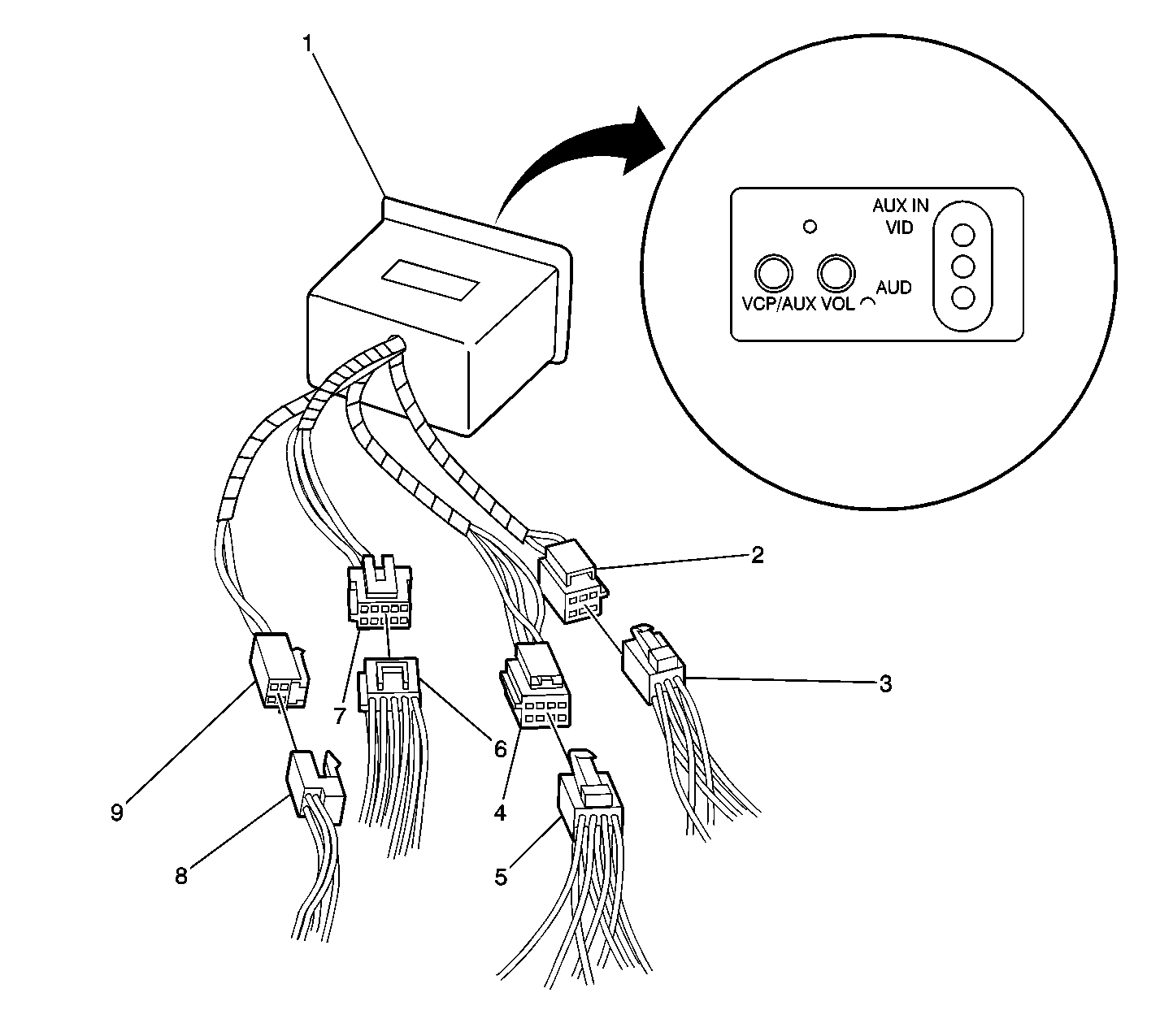
Figure 25:

Auxiliary Module


Object Number: 416780  Size: LF
(1)Auxiliary Module (AM)
(2)AM Connector C2 (6 Cavities) (GRY) -- Pigtail (Male)
(3)AM Connector C2 (6 Cavities) (GRY) (Female) -- To Video Screen
(4)AM Connector C4 (8 Cavities) (BLU) Pigtail (Male)
(5)AM Connector C4 (8 Cavities) (BLU) (Female) -- To Interface Module
(6)AM Connector C1 (10 Cavities) (NAT) (Male) -- To VCP Harness
(7)AM Connector C1 (10 Cavities) (NAT) Pigtail (Female)
(8)AM Connector C3 (4 Cavities) (BLK) (Female) -- to Interface Module
(9)AM Connector C3 (4 Cavities) (BLK) Pigtail (Male)
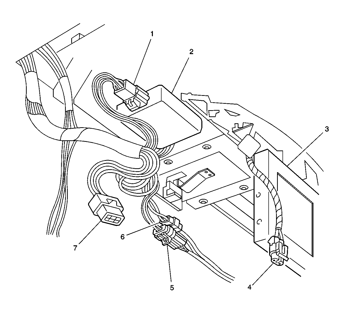
Figure 26:

Interface Module


Object Number: 416775  Size: LF
(1)Interface Module (IM) Connector
(2)Interface Module (IM)
(3)Video Screen
(4)Auxiliary Video Module (AVM) Connector C1 (NAT) -- Video Screen
(5)C328 (8 Cavities)
(6)C326 (4 Cavities)
(7)Rear Seat Heater-A/C Control Connector
Figure 27:

Fuel Tank, Below LH Side, Middle of Vehicle
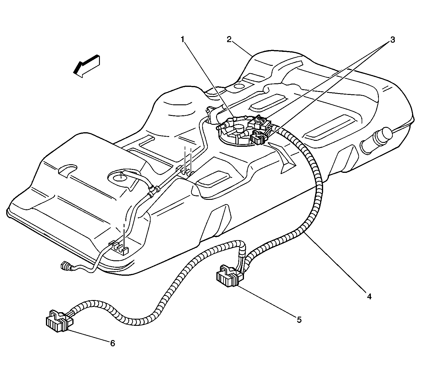

Object Number: 447388  Size: LF
(1)Fuel Sender
(2)Fuel Tank
(3)Fuel Tank C1 and C2 Connectors
(4)Fuel Sender Harness
(5)In-line Connector C305
(6)Evaporative Emission (EVAP) Canister Vent Solenoid
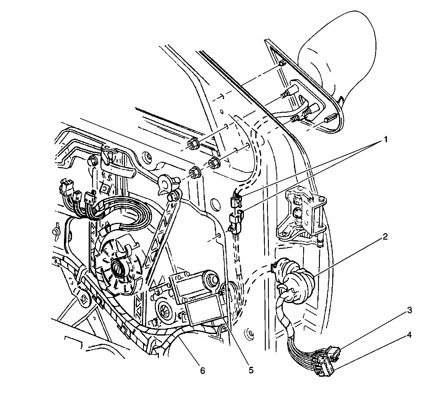
Figure 28:

LF Door (RH Side Similar)


Object Number: 447244  Size: LF
(1)Pigtail Connector to Outside Rearview Mirror-Driver Motor Pack (RH Side Similar)
(2)Pass Through P500 (P600 Similar)
(3)In-line Connector C301 (C302, RH Side Similar)
(4)In-line Connector C303 (C304, RH Side Similar)
(5)Window Motor-Driver (RH Similar)
(6)LF Door Harness (RH Similar)
Figure 29:

Underneath Rear of Vehicle


Object Number: 447324  Size: LF
(1)In-line Connector C309, Electronic Brake Control (ECBM) Harness to Wheel Speed Sensor (WSS)-LR Harness
(2)Electronic Brake Control Harness
(3)In-line Connector C306, Electronic Brake Control (ECBM) Harness to RR Wheel Speed Sensor (WSS)-RR Harness
Figure 30:

LH Taillamp (RH Similar)


Object Number: 447259  Size: LF
(1)Connector to Taillamp-Left
(2)Body Harness
(3)Pass Through P401 (P400 Similar)
(4)Taillamp-Left
Figure 31:

Top, LH Side of Rear Body


Object Number: 447274  Size: LF
(1)Liftgate (Open Position)
(2)Liftgate Harness
(3)Body Harness
(4)In-Line Connector C401
(5)In-Line Connector C403
(6)Pass Through P405 (P406 Similar)
(7)LH Rear Body