For 1990-2009 cars only
Removal Procedure
- Remove the intake manifold cover. Refer to Intake Manifold Cover Replacement.
- Remove the tire and wheel. Refer to Tire and Wheel Removal and Installation.
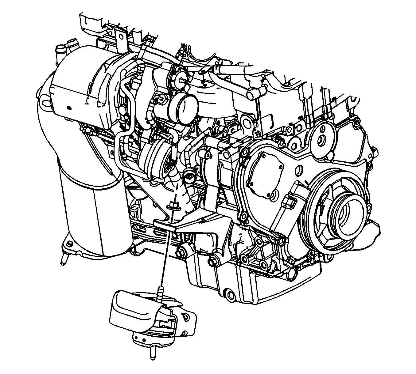
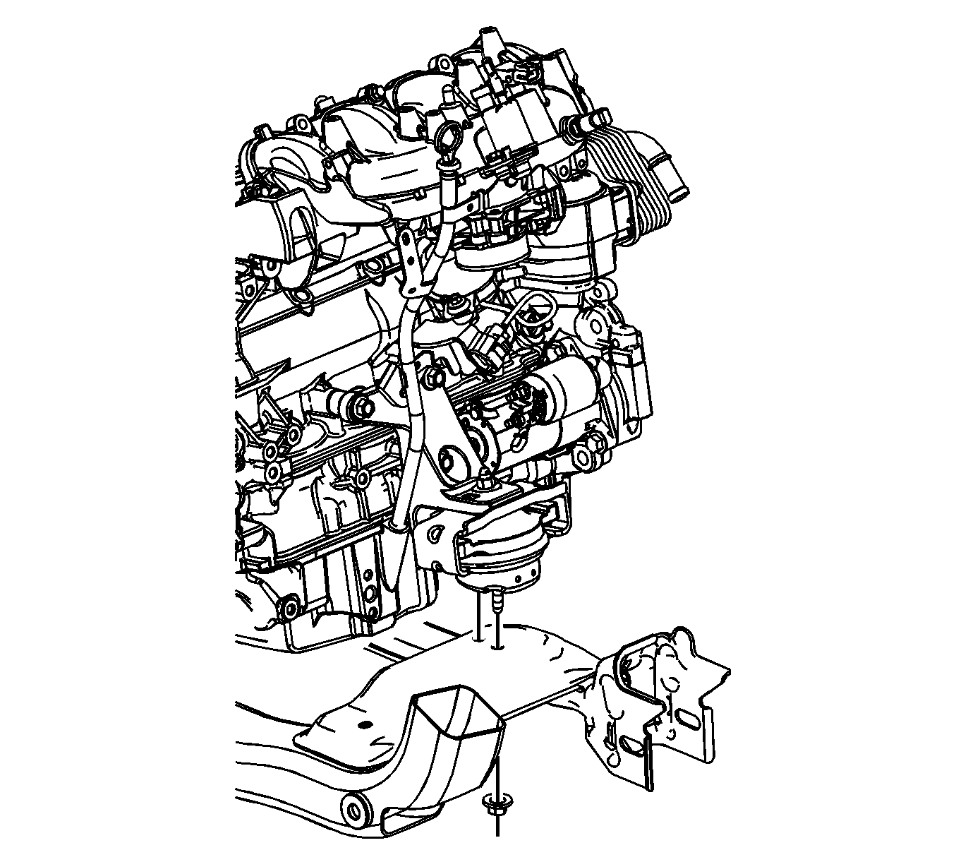
- Remove the right engine mount upper nut.
- Raise and support the vehicle. Refer to Lifting and Jacking the Vehicle.
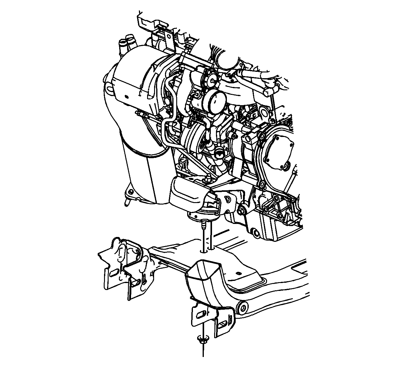
- Remove the right engine mount lower nut.
- Remove the left engine mount lower nut.
- Remove the right brake hose bracket bolt.
- Remove the right brake line clip at the crossmember.
- Position an adjustable jack below the oil pan. Place a block of wood between the oil pan and the jack.
- Raise the engine using the adjustable jack until the engine mount can be removed.
- Remove the right engine mount.


Installation Procedure
- Install the right engine mount.
- Lower the engine using the adjustable jack until the engine is resting on the mount.
- Remove the adjustable jack from below the oil pan.
- Install the right brake line clip at the crossmember.
- Install the right brake hose bracket bolt and tighten to 10 N·m (89 lb in).
- Install the left engine mount lower nut and tighten to 55 N·m (41 lb ft).
- Install the right engine mount lower nut and tighten to 55 N·m (41 lb ft).
- Lower the vehicle.
- Install the right engine mount upper nut and tighten to 55 N·m (41 lb ft).
- Install the tire and wheel. Refer to Tire and Wheel Removal and Installation.
- Install the intake manifold cover. Refer to Intake Manifold Cover Replacement.

Caution: Refer to Fastener Caution in the Preface section.


