Note: Lubricate all bearings with transmission fluid during assembly.
- Install 2 bolts, with nuts, in the lower holes of the intermediate case. The bolts will be used to hold the intermediate case in a vise during assembly.
Caution: Refer to Machined Surface Damage Caution in the Preface section.
- Mount the intermediate case in a vise on the previously installed bolts.
Caution: Refer to Fastener Caution in the Preface section.
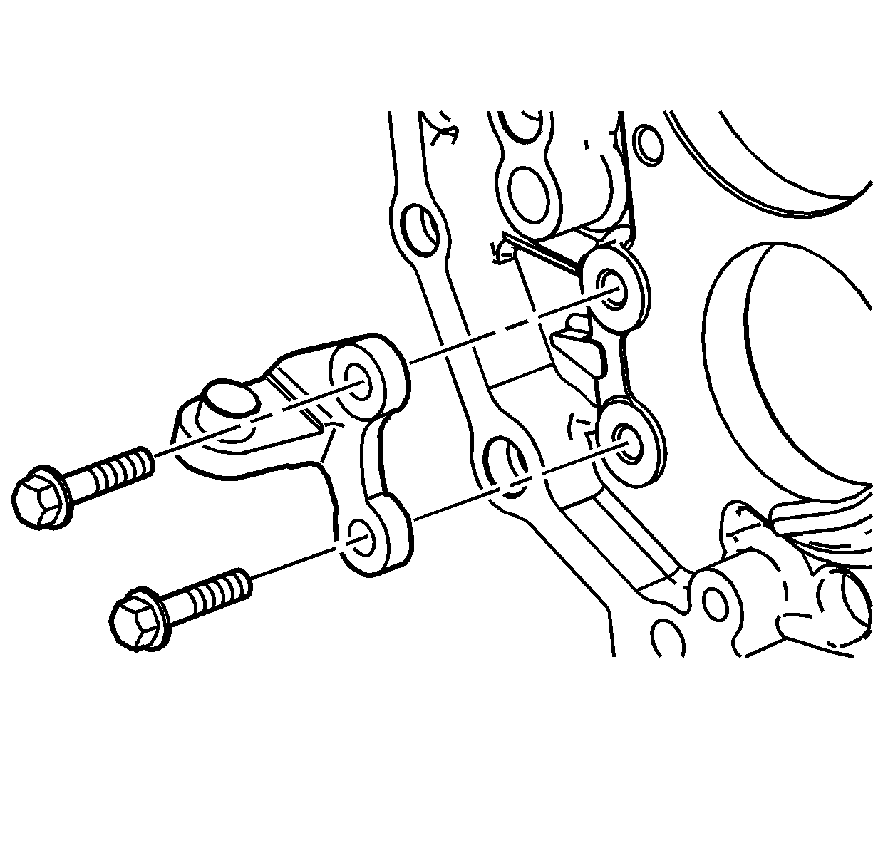
- Install the reverse shift fork bracket with bolts and tighten to
18 N·m (13 lb ft).
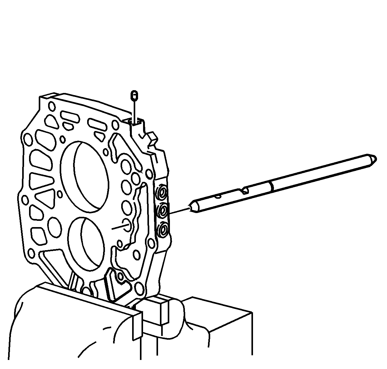
- Install the reverse gear shift shaft.
- Turn the shift shaft to align the interlock hole facing up.
- Using a magnet, install the reverse shift shaft interlock.
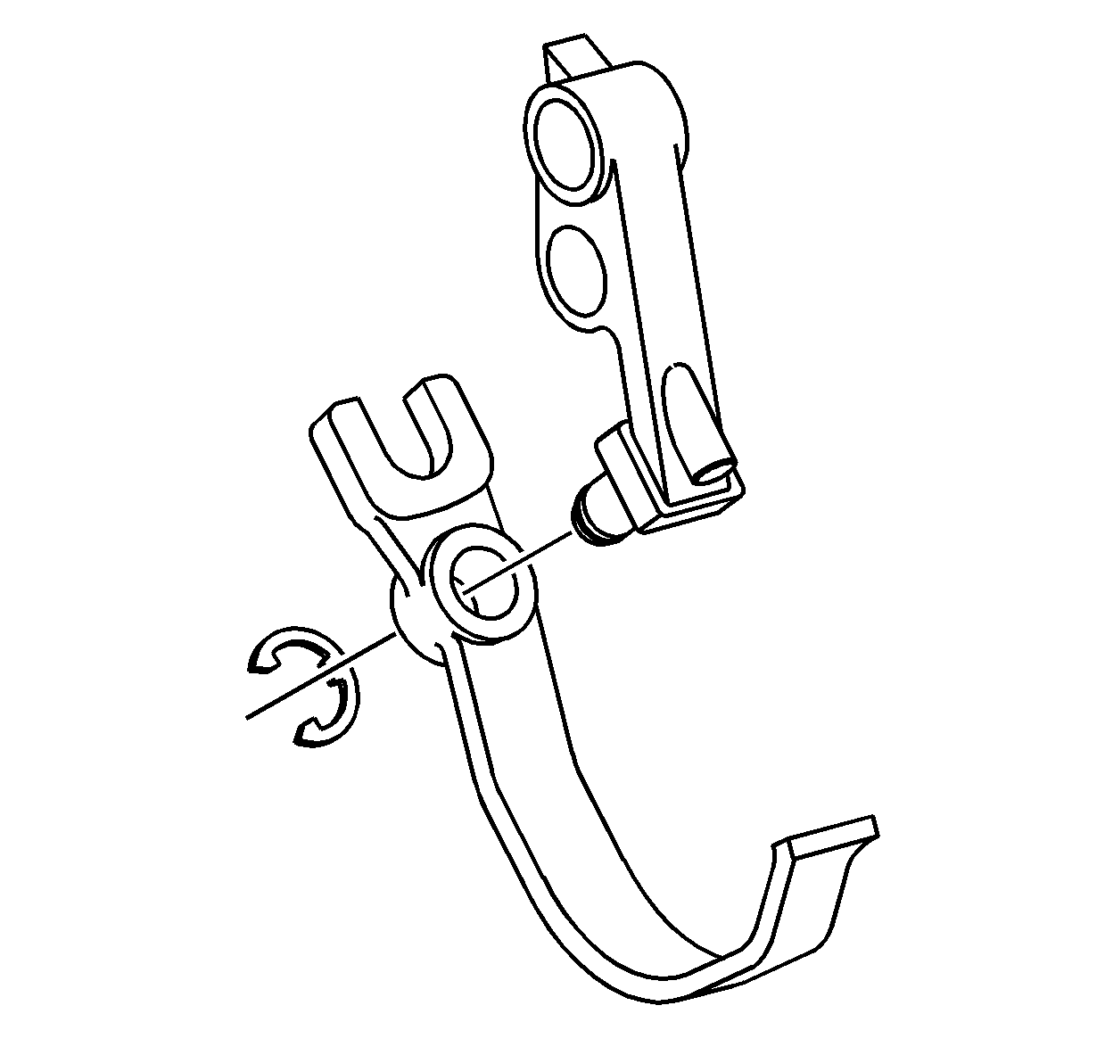
- Install the reverse shift fork on the reverse shift lever.
- Install the reverse shift fork retaining ring.
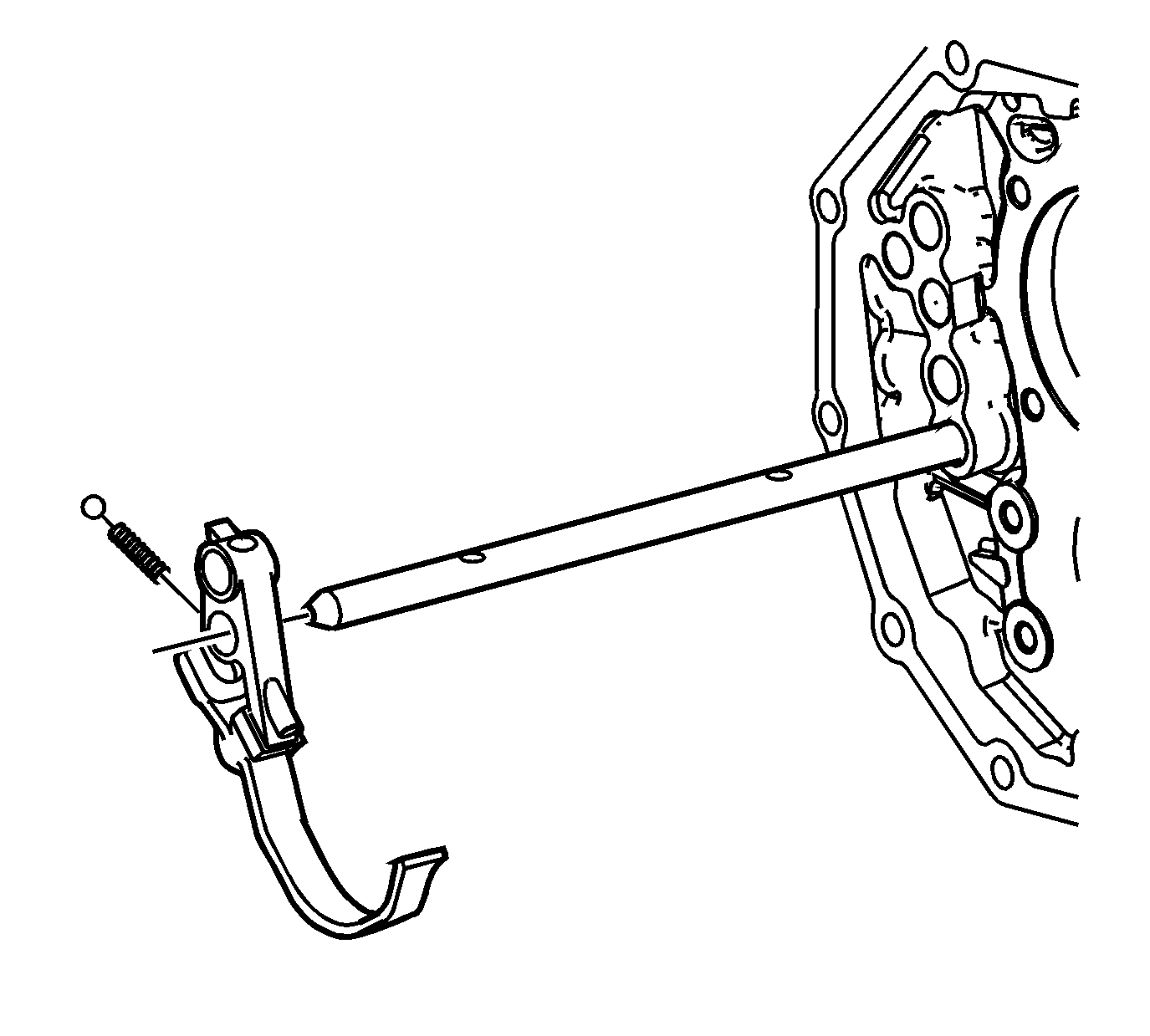
- Install the reverse shift lever on the reverse shift shaft.
| 9.1. | Install the detent spring in the lever. |
| 9.2. | Install the detent ball. Push the ball in while sliding the lever on the shaft. |
| 9.3. | Slide the lever on the shaft until the detent ball is located in the detent on the shaft. |
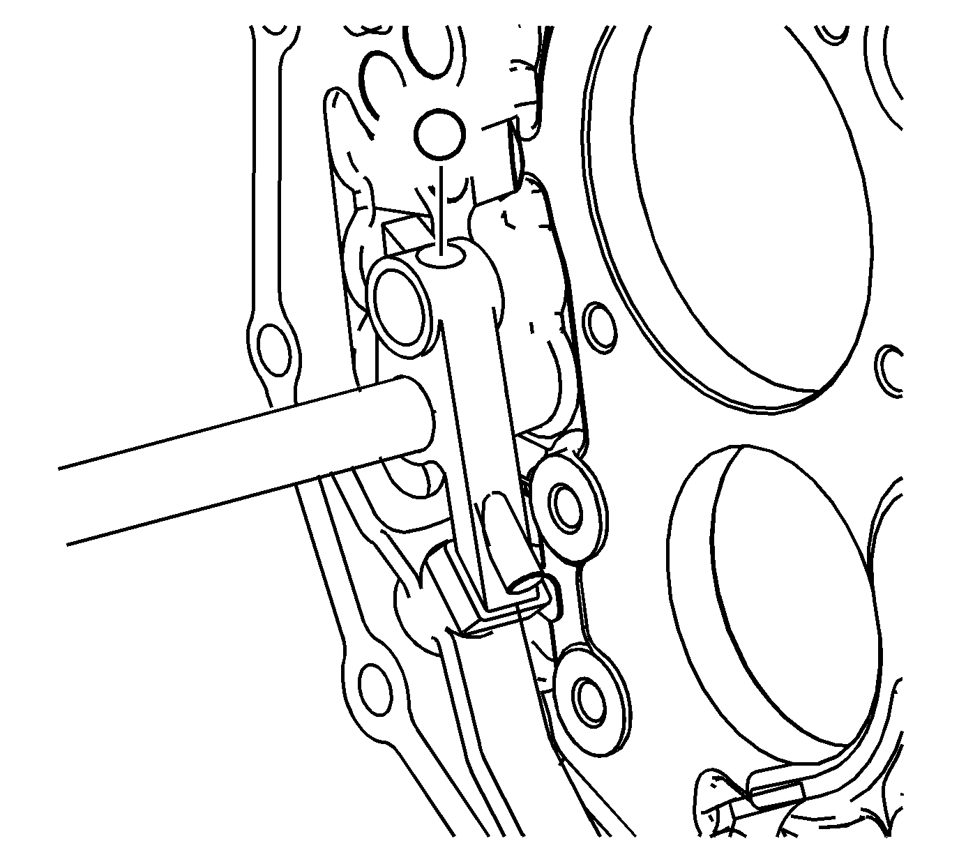
- Install the detent ball in the reverse shift lever for the 5th shift shaft.
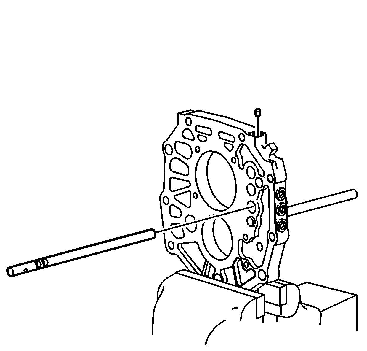
- Install the 5th shift shaft into the intermediate case.
- Push down on the detent ball in the reverse shift lever and install the 5th shift shaft.
- Align the 5th shift shaft with the detents facing toward the detent ball hole at the side of the case.
- Using a magnet, install the 1st/2nd shift shaft and 5th shift shaft interlock pin.
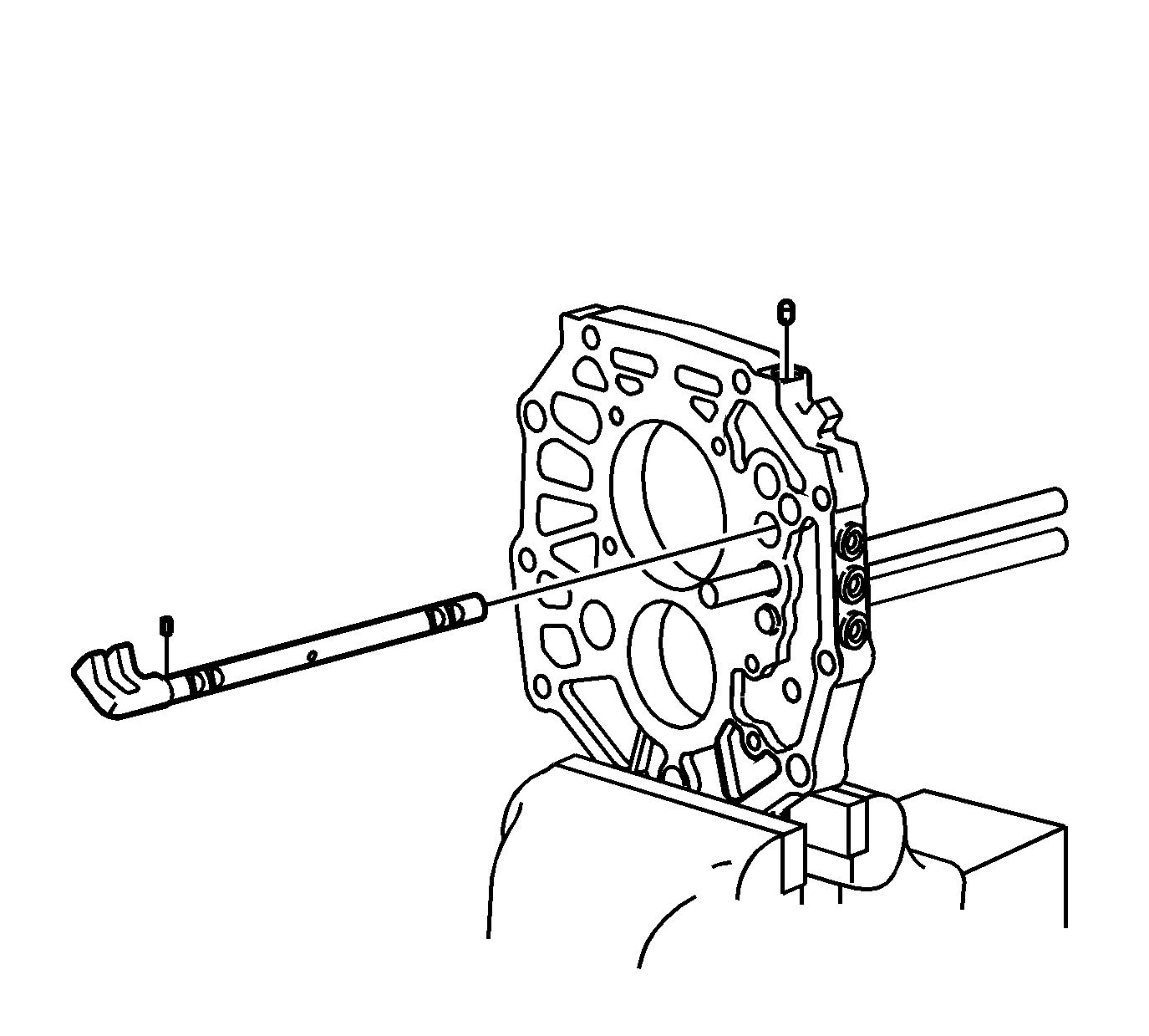
- Install the small interlock pin in the 1st/2nd shift shaft.
- Install the 1st/2nd shift shaft. Ensure to align the interlock pin with the interlock in the 5th shift shaft and the detents toward the detent ball hole in the side of the case.
- Using a magnet, install the 1st/2nd shift shaft and 3rd/4th shift shaft interlock pin.
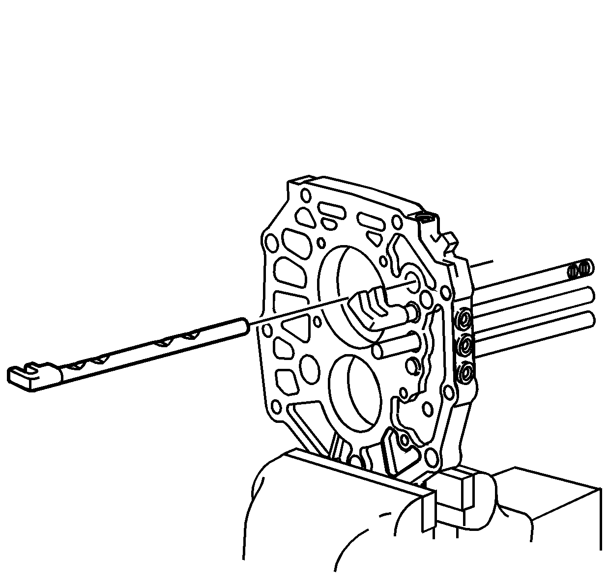
- Install the 3rd/4th shift shaft. Align the detents on the shaft toward the detent ball holes at the top of the case.
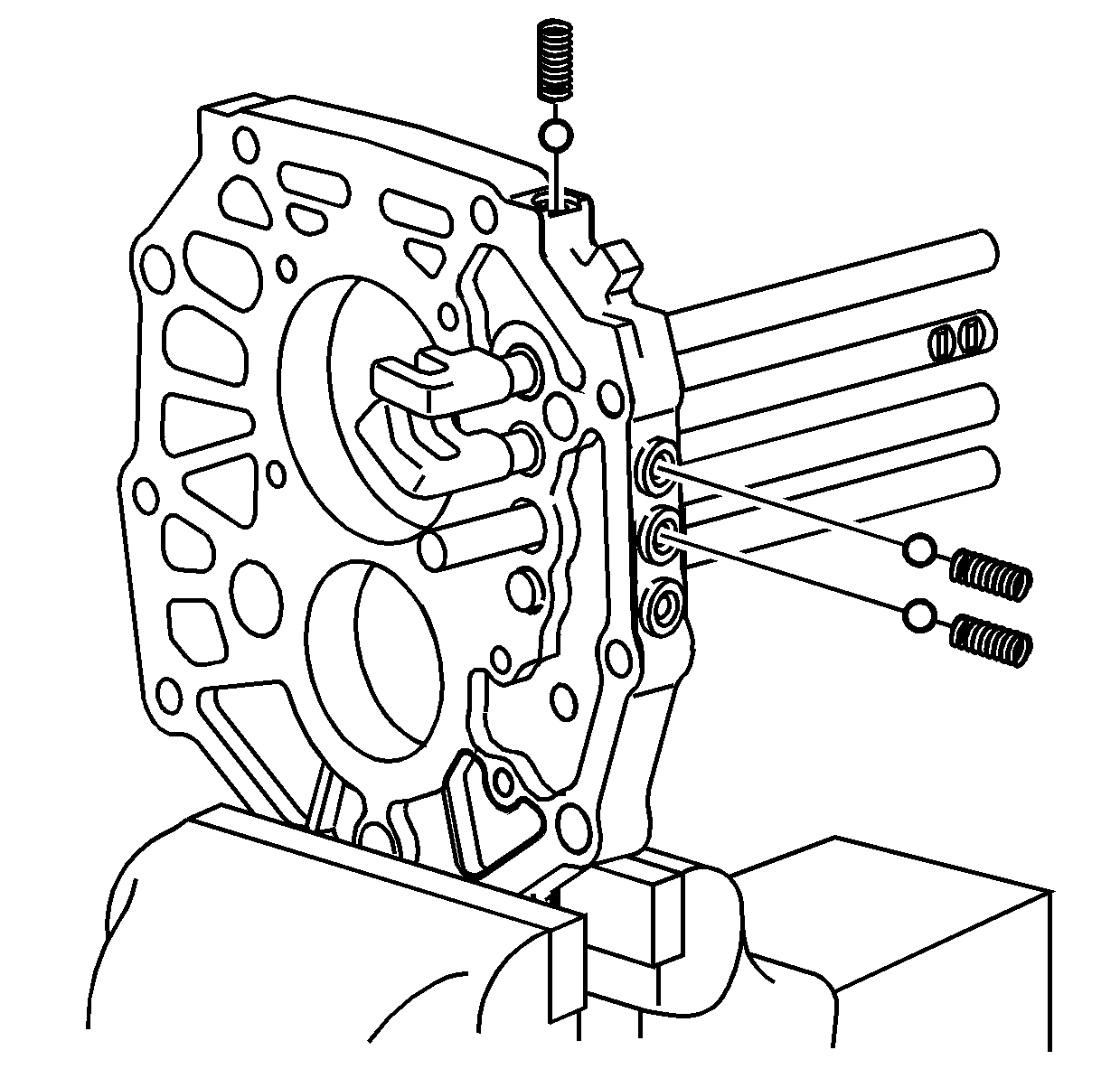
- Install the 5th shift shaft detent spring and ball. The reverse gear shift shaft does not have a detent spring and ball in the plug opening.
- Install the 3rd/4th shift shaft detent spring and ball.
- Install the 1st/2nd shift shaft detent spring and ball.
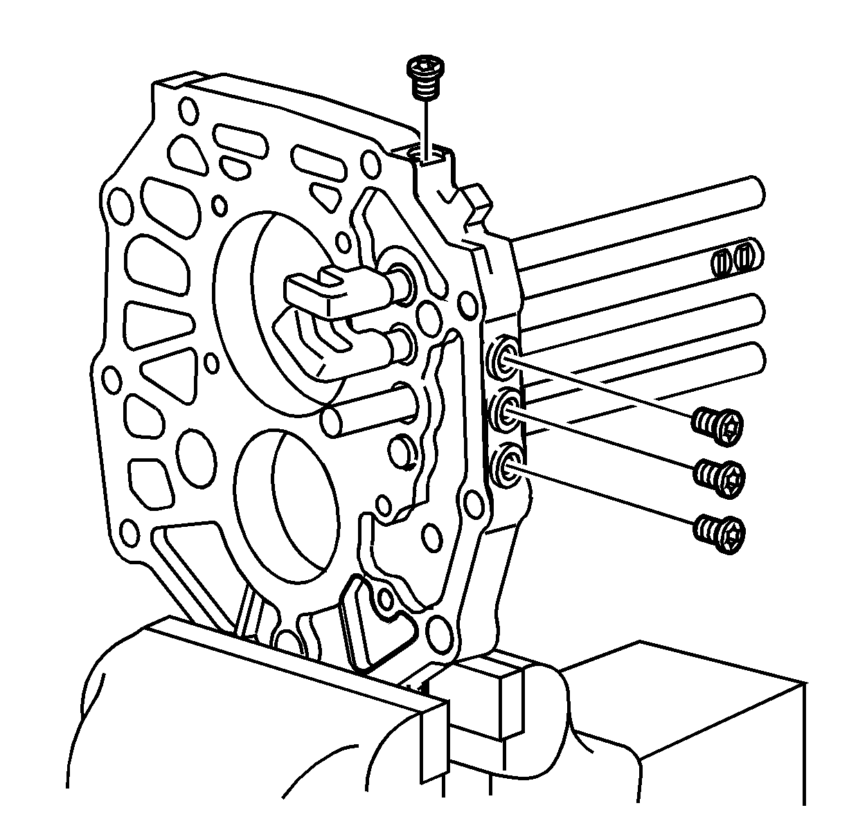
Note: The shift detent plugs must not be used again. Always install new plugs.
- Install the 4 NEW shift detent plugs for the balls and springs and tighten to
19 N·m (14 lb ft).
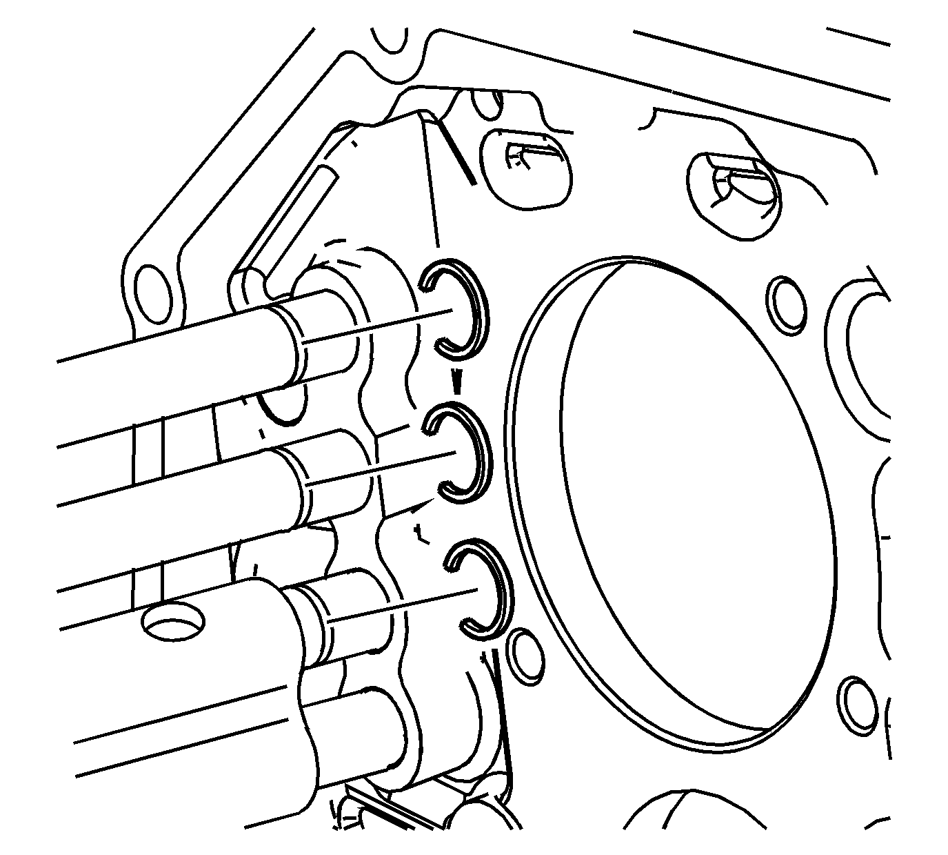
Note:
| • | Always use new retaining rings. |
| • | Do not install the retaining ring for the reverse shift shaft at this time. |
- Install the 1st/2nd shift shaft retaining ring.
- Install the 3rd/4th shift shaft retaining ring.
- Install the 5th shift shaft retaining ring.
- Move the shift shafts in the NEUTRAL position.
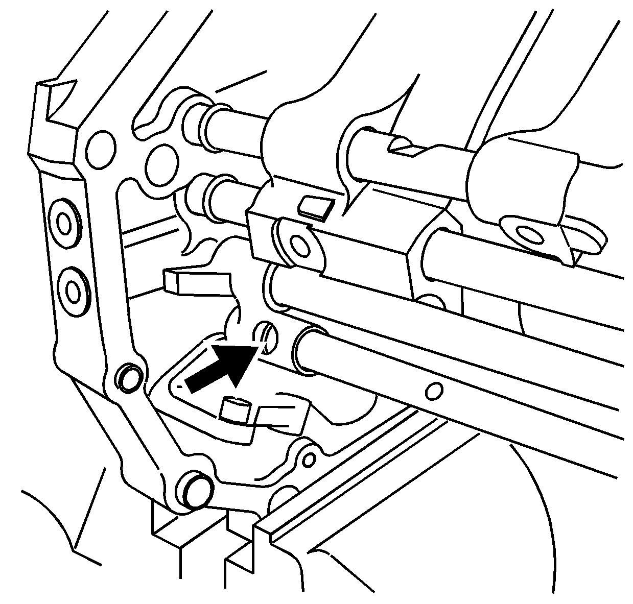
- Shift the reverse shift shaft forward.
- Move the reverse shift lever forward past the retaining ring groove on the reverse shift shaft. This allows the output shaft to clear the reverse shift fork during installation.
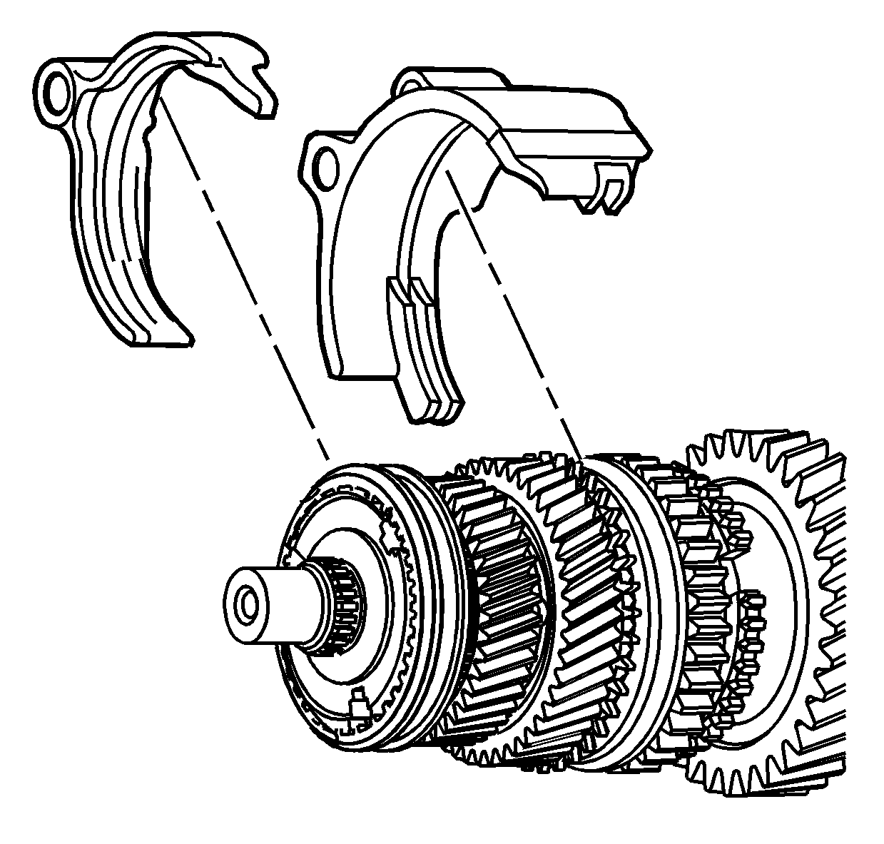
- Position the 3rd/4th shift fork and the 1st/2nd shift fork on the synchronizer sleeves. To aid during assembly, hold the shift forks in place with rubber bands.
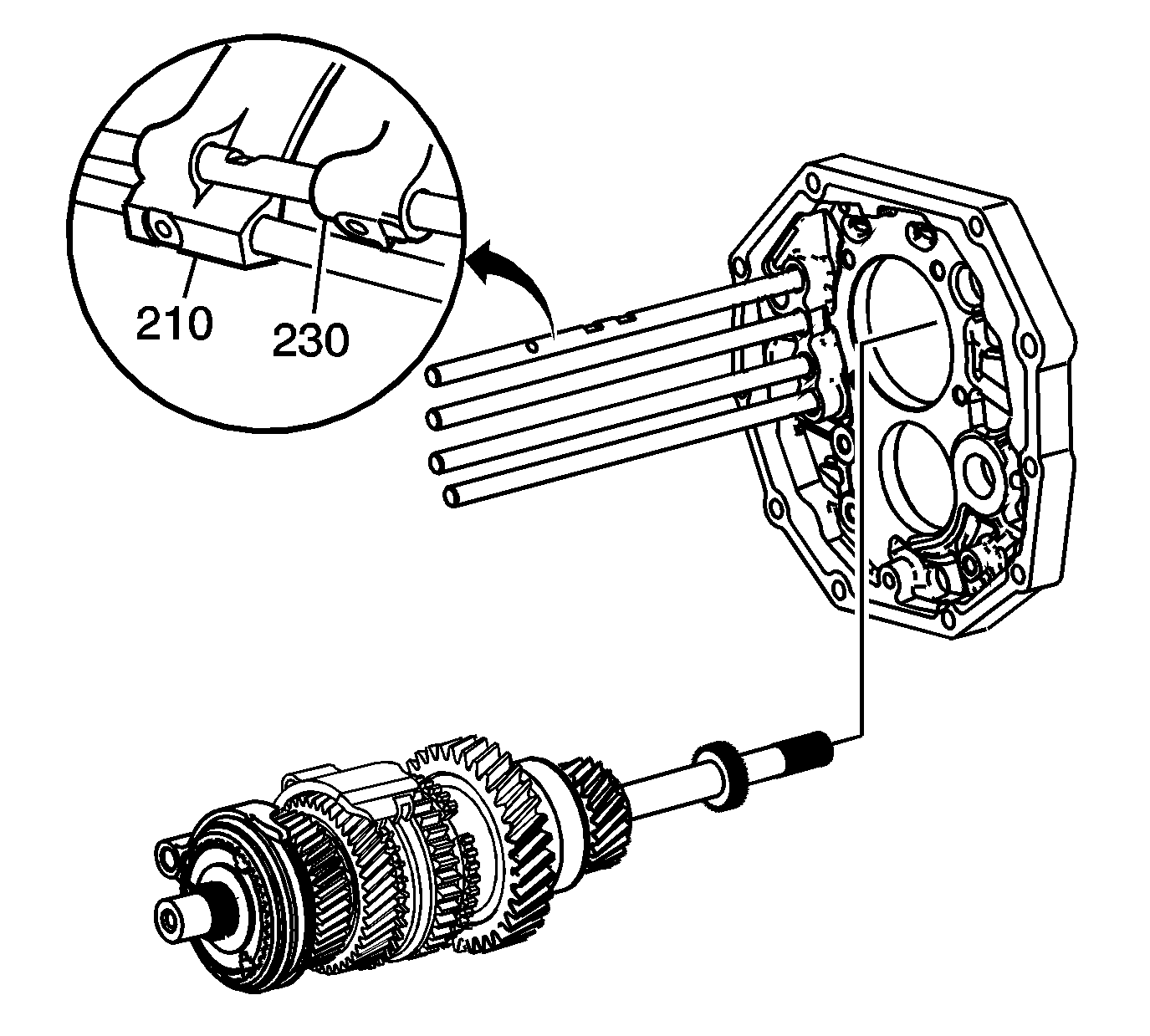
- Install the output shaft assembly.
| • | Hold the 1st/2nd shift fork (210) and the 3rd/4th shift fork (230) in position to the output shaft. |
| • | While installing the output shaft, slide the 1st/2nd shift fork (210) and the 3rd/4th shift fork (230) on the shift shafts. |
| • | The 1st/2nd shift fork (210) goes on the top 2 shift shafts. |
| • | The 3rd/4th shift fork (230) goes on the top shaft. |
| • | Wiggle the output shaft assembly to install the output shaft rear bearing in the intermediate case. |
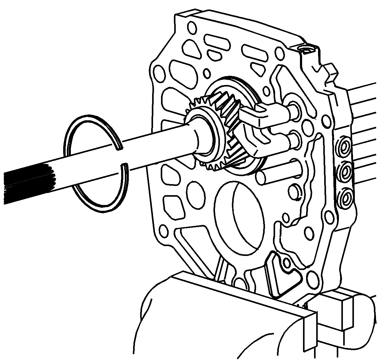
- Install the output shaft rear bearing outer retaining ring.
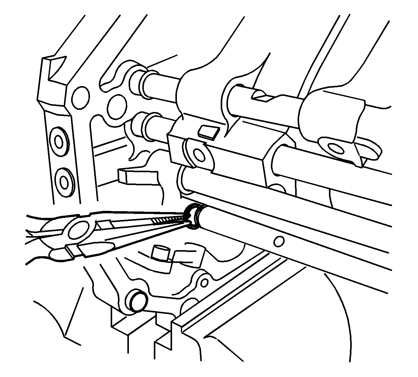
- Move the reverse shift lever and the shift shaft to the NEUTRAL position.
- Install a new retaining ring for the reverse shift lever on the reverse shift shaft.
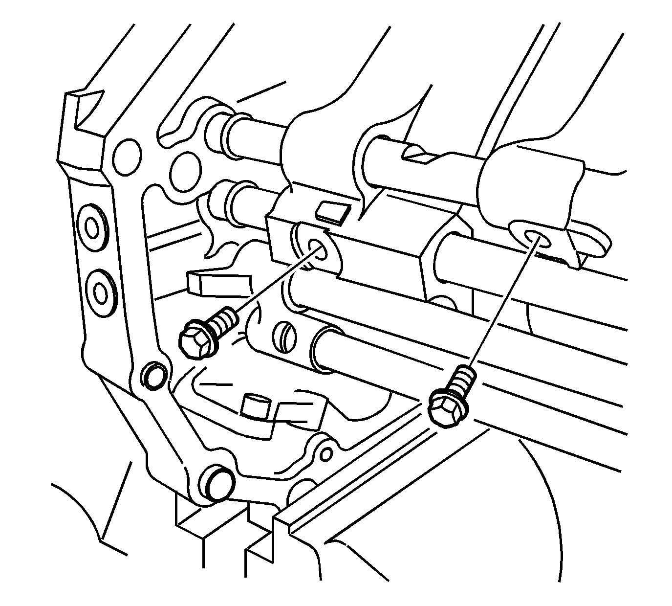
Note: The shift fork bolts must not be used again. Always install new shift fork bolts.
- Install the 1st/2nd shift fork bolt and tighten to
20 N·m (14 lb ft).
- Install the 3rd/4th shift fork bolt and tighten to
20 N·m (14 lb ft).
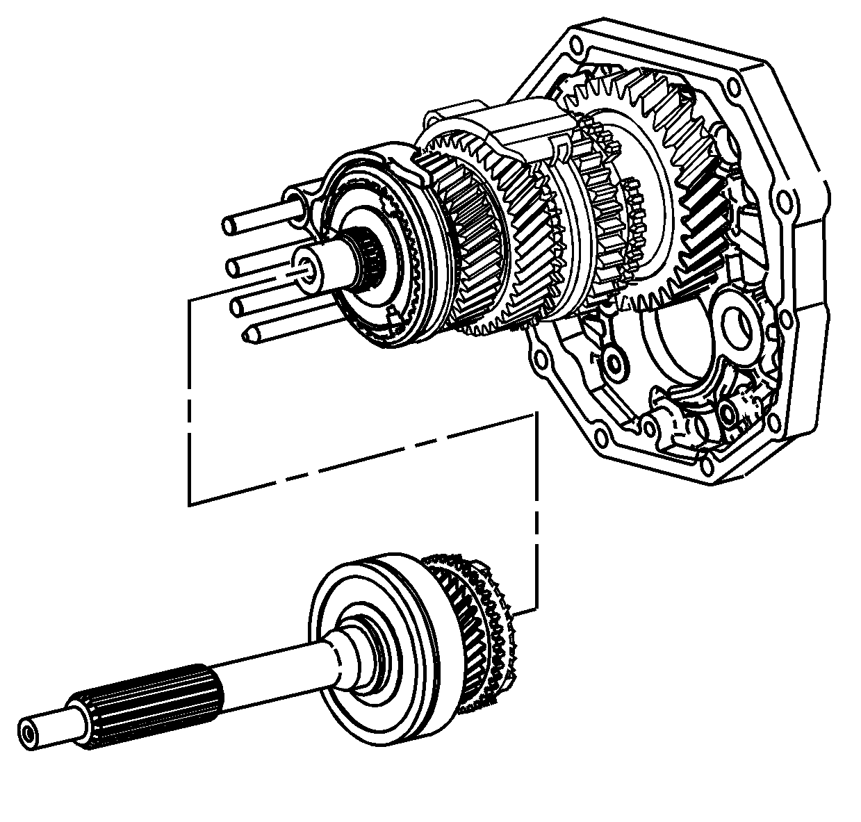
- Install the input shaft assembly, with the output shaft front support bearing and the 4th gear blocking ring, to the output shaft. Ensure to align the tabs on the blocking ring to the notches in the synchronizer hub.
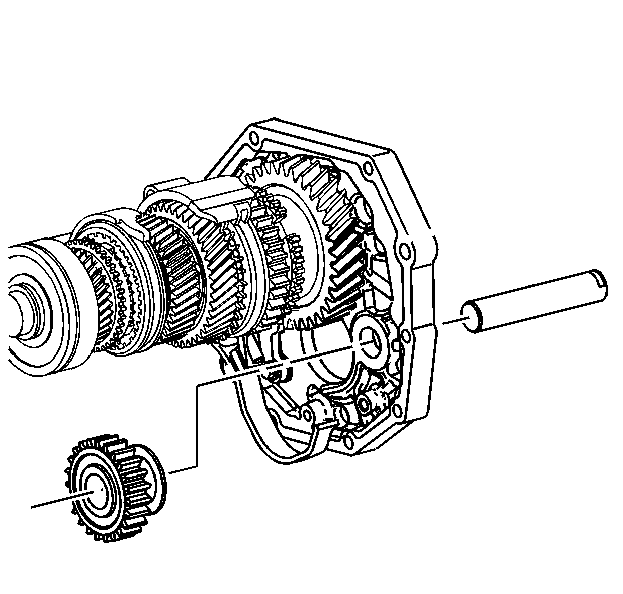
- Install the reverse gear idler shaft and reverse idler gear.
| • | Ensure the reverse shift fork is in position on the reverse gear. |
| • | The slot on the reverse gear idler shaft aligns facing upward. |
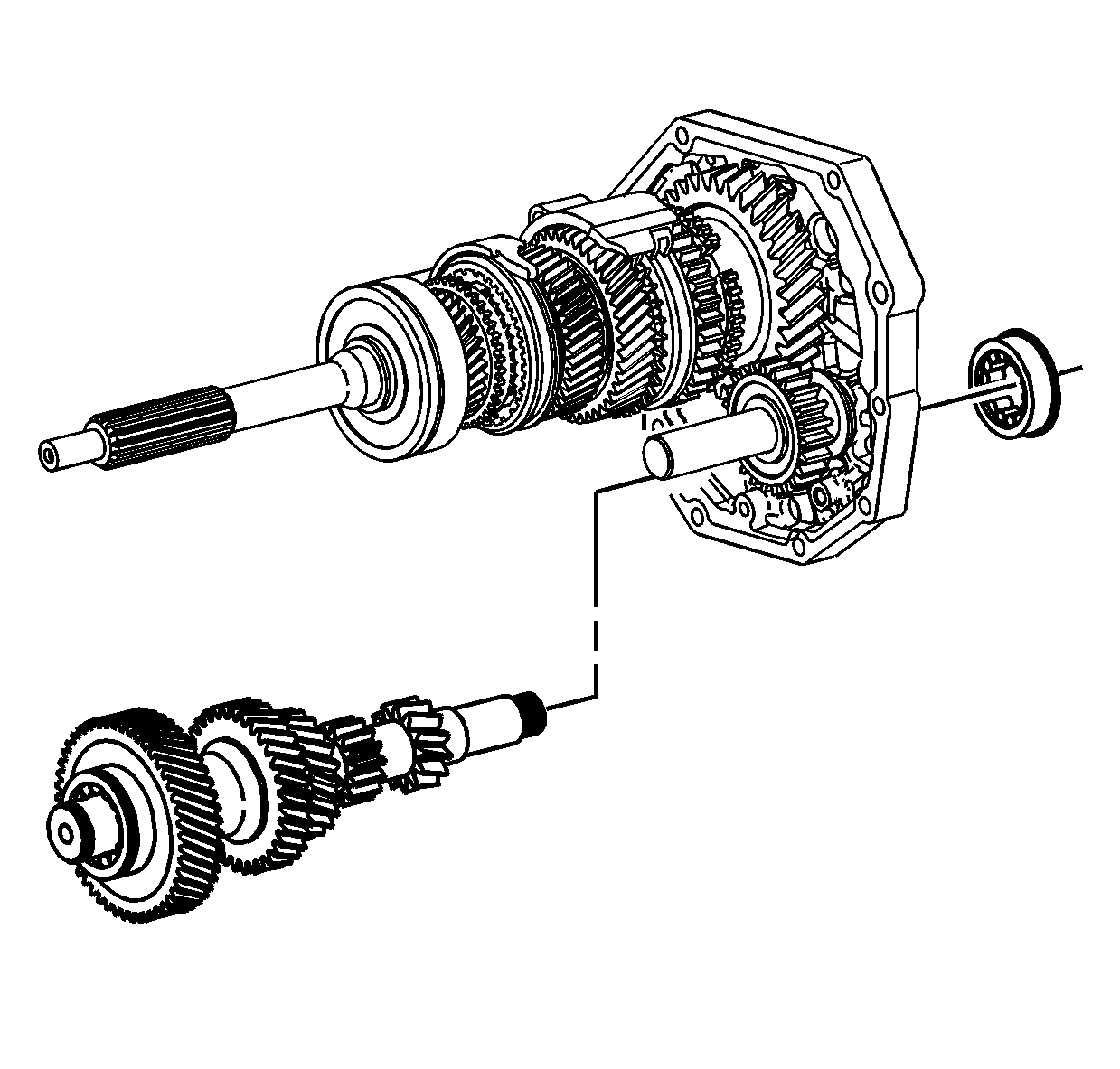
- Install the countershaft in position.
- Install the countershaft rear bearing. Hold the countershaft in the correct position against the output shaft gears. The bearing will slide in the case.
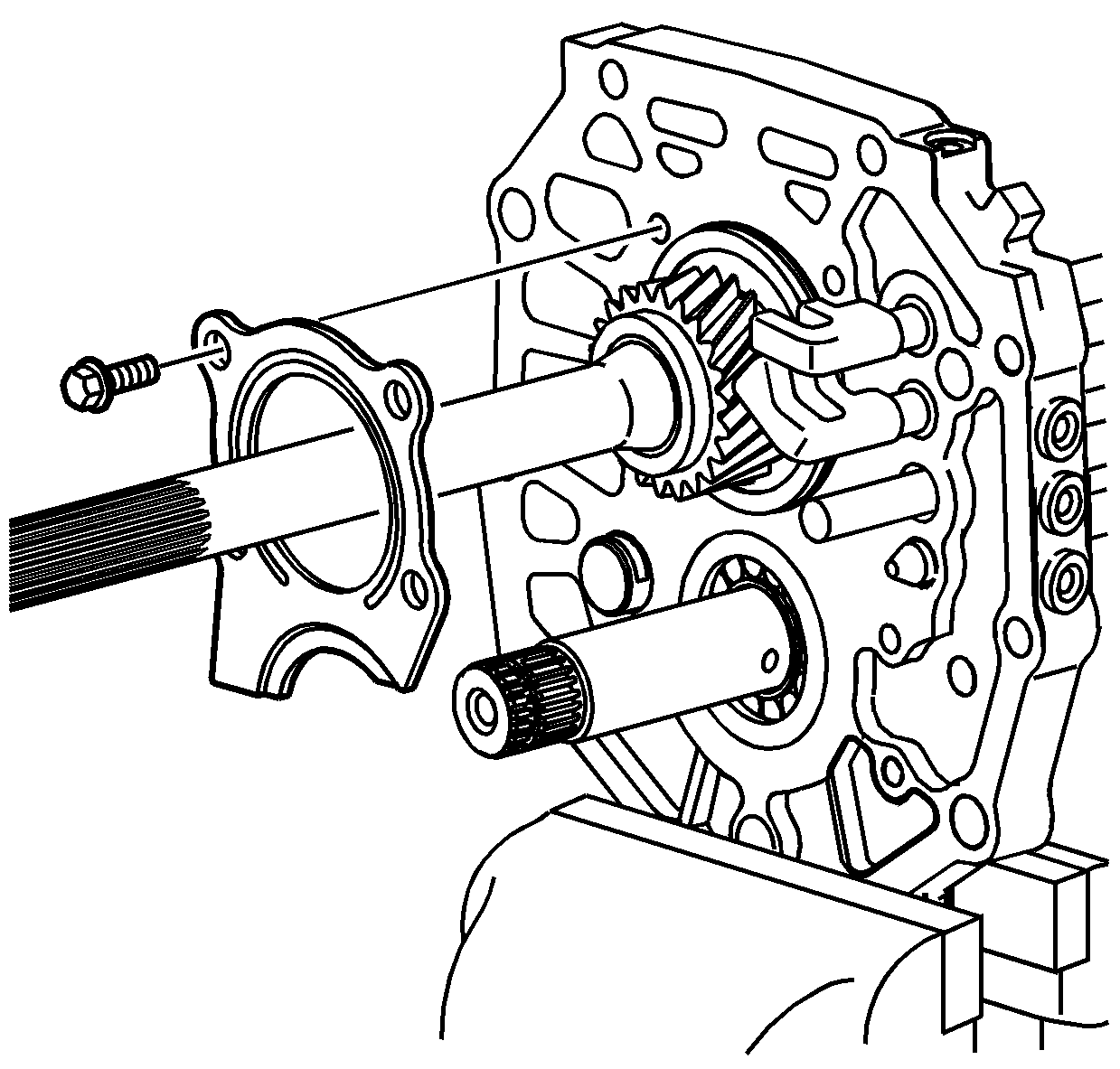
- Apply threadlocker GM P/N 12345382 (Canadian P/N 10953489) to the threads of the rear bearing retainer bolts.
- Install the rear bearing retainer. The retainer installs in the slot on the reverse gear idler shaft.
- Install the rear bearing retainer bolts and tighten to
18 N·m (13 lb ft).
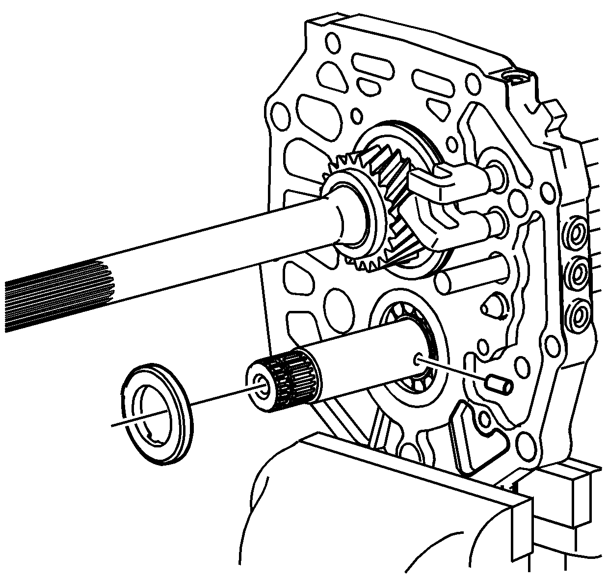
- Install the thrust washer lock pin.
- Install the 5th gear thrust washer. The tapered edge side of the thrust washer goes toward the countershaft bearing.
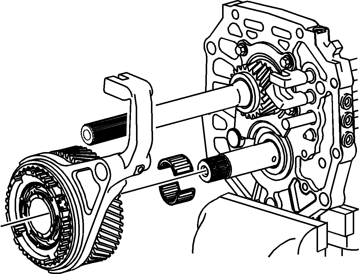
- Install the 5th countershaft gear bearing and 5th/reverse synchronizer assembly onto the countershaft.
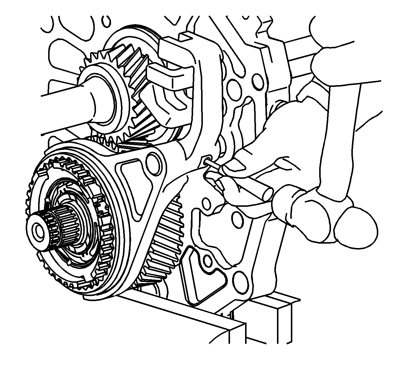
- Using a hammer and a punch, install a new 5th shift fork roll pin.
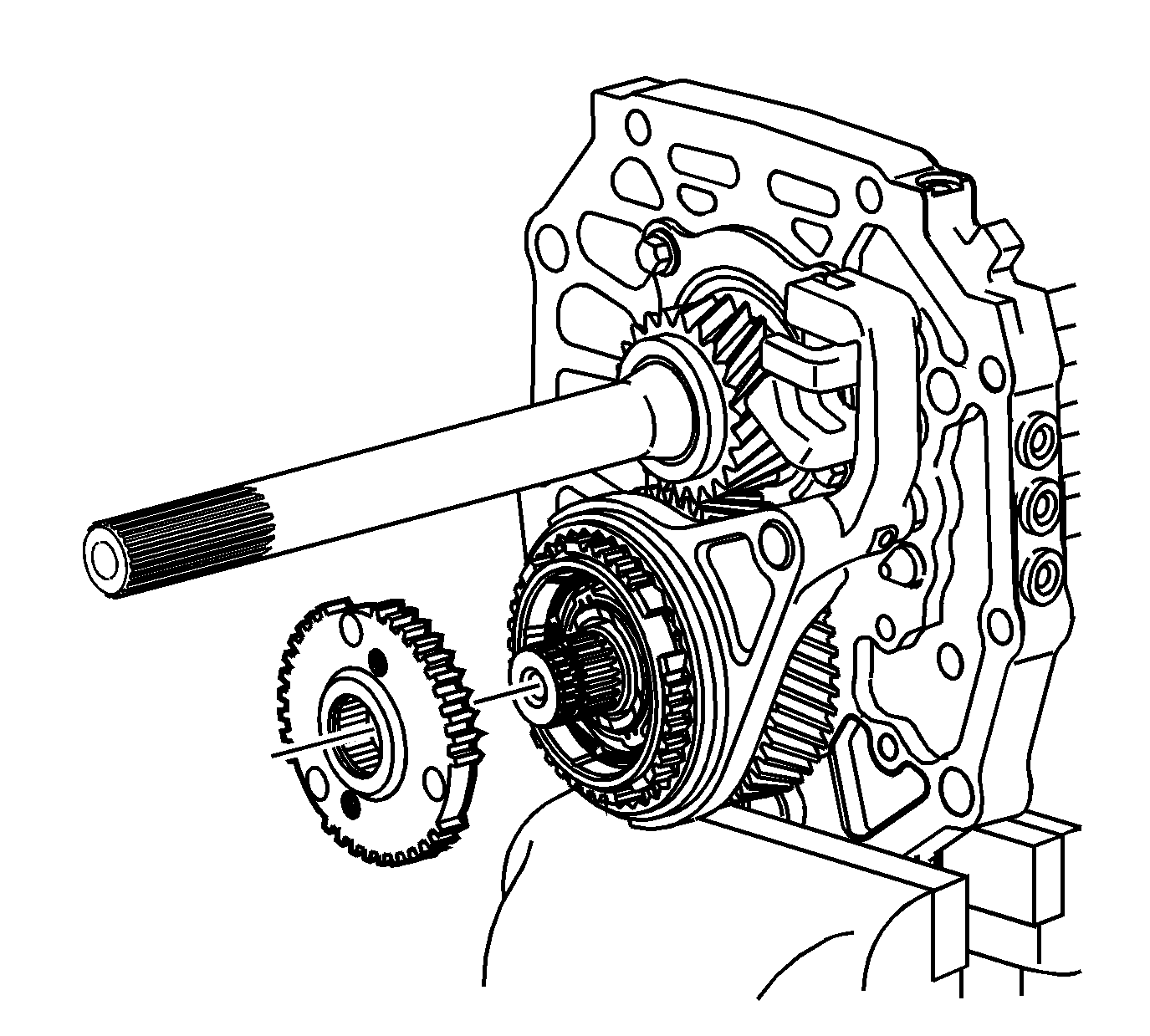
Note: When installing the 5th synchronizer gear, ensure to align with the holes for the reverse internal blocking ring tabs. Do not rotate the blocking rings to align with the gear. Rotating the blocking rings would move the rings from
the lock position. If the rings become unlocked, the 5th/reverse synchronizer would have to be removed and assembled again.
- Place the 5th synchronizer gear on the countershaft in the following position:
| • | The holes in the gear align with the tabs on the reverse internal blocking ring. |
| • | The machined side of the hub goes forward, the cut point teeth side forward. |
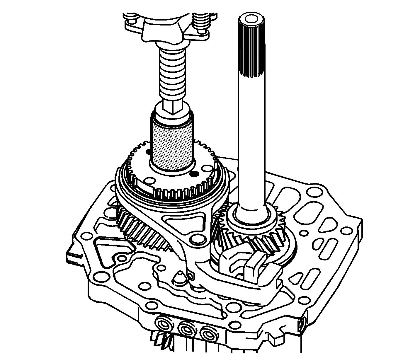
Note: Support the front of the countershaft on a press plate. Ensure that the tabs on the blocking ring align in the gear holes. Do not rotate the blocking rings for aligning.
- Using a hydraulic press and
J 39924-2 installer
or equivalent, install the 5th synchronizer gear.
- Inspect the 5th/reverse synchronizer assembly for proper installation. The blocking rings should move freely back and forth. If the blocking rings do not move, the rings came out of the lock position. Disassembly is required. Assemble again properly.
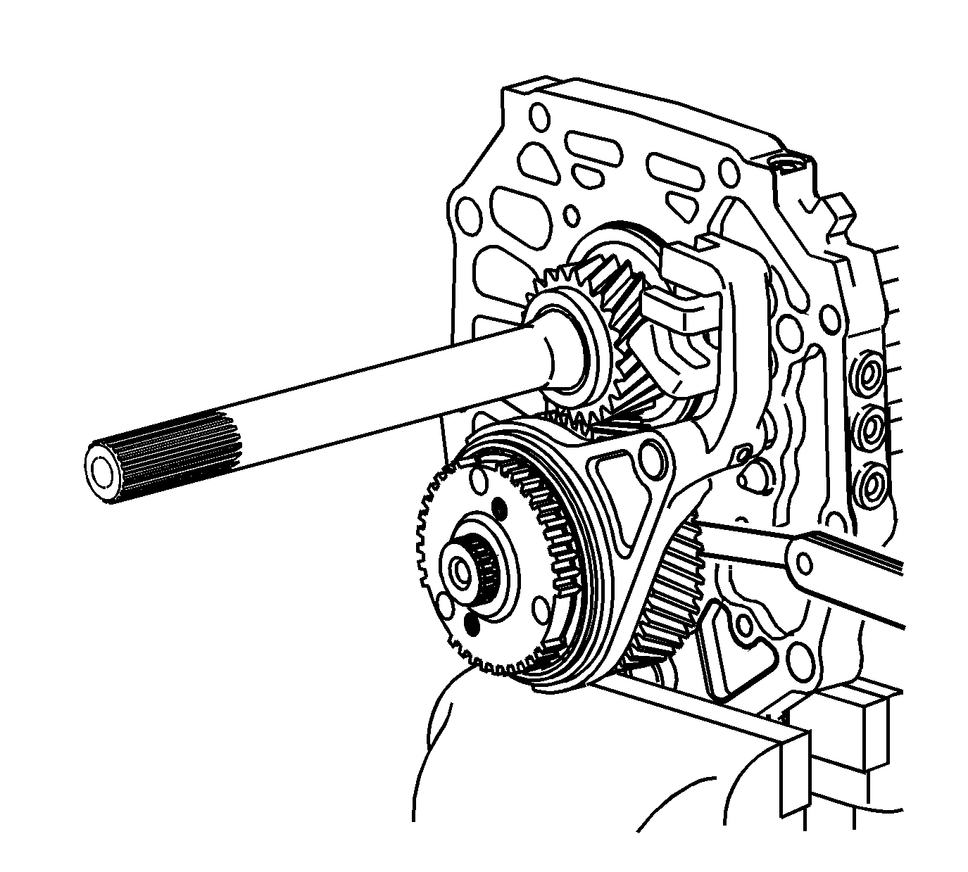
- Using a feeler gage between the 5th gear and the thrust washer, measure the axial clearance.
Specification
| • | Standard Clearance: 0.10-0.35 mm (0.0039-0.0138 in) |
| • | Maximum Clearance: 0.40 mm (0.0157 in) |
- If the clearance exceeds the maximum, ensure the 5th synchronizer gear is installed completely.
- If the clearance exceeds the maximum, inspect the 5th countershaft gear, the countershaft, or the thrust washer for wear.
- If clearance is lower than the standard clearance, inspect the 5th countershaft gear, the countershaft, or the 5th synchronizer gear for burrs.
- Repair or replace the damaged or worn component.
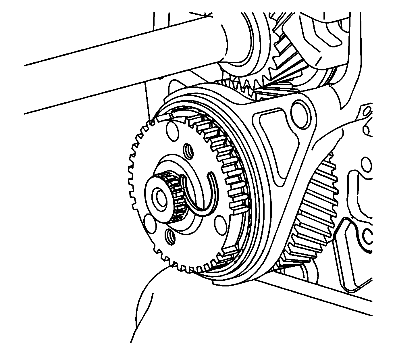
Note: The retaining ring is a select fit. Always install a NEW retaining ring.
- Select the maximum thickness retaining ring for the 5th gear, that will fit. Refer to
Fifth Gear Retaining Ring Specifications.
- Install the 5th synchronizer gear retaining ring.
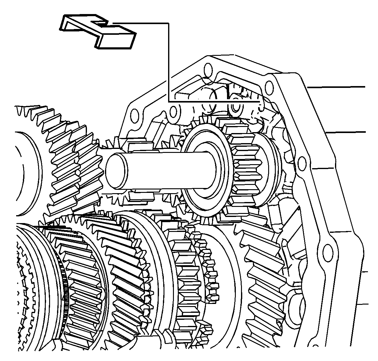
- Install the magnet.
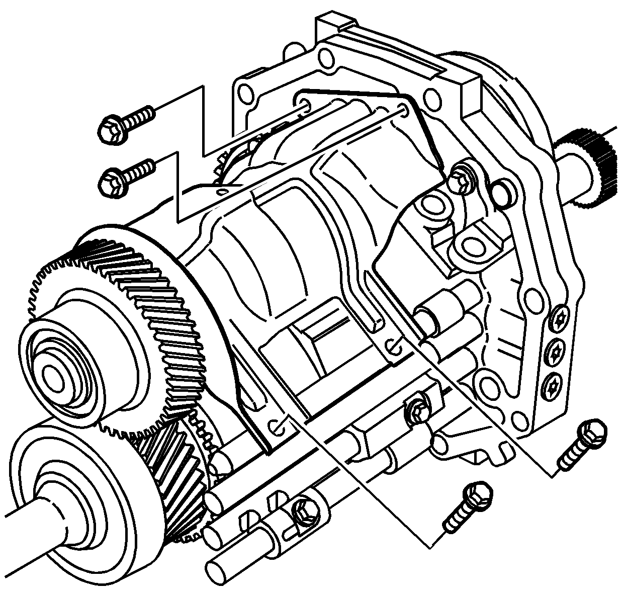
- Apply threadlocker GM P/N 12345382 (Canadian P/N 10953489) to the threads of the oil baffle bolts.
- Install the oil baffle.
- Install the oil baffle bolts.
| • | Tighten the oil baffle bolts to the intermediate case
to 20 N·m (14 lb ft). |
| • | Tighten the oil baffle bolts to the shift shaft to
13 N·m (10 lb ft). |
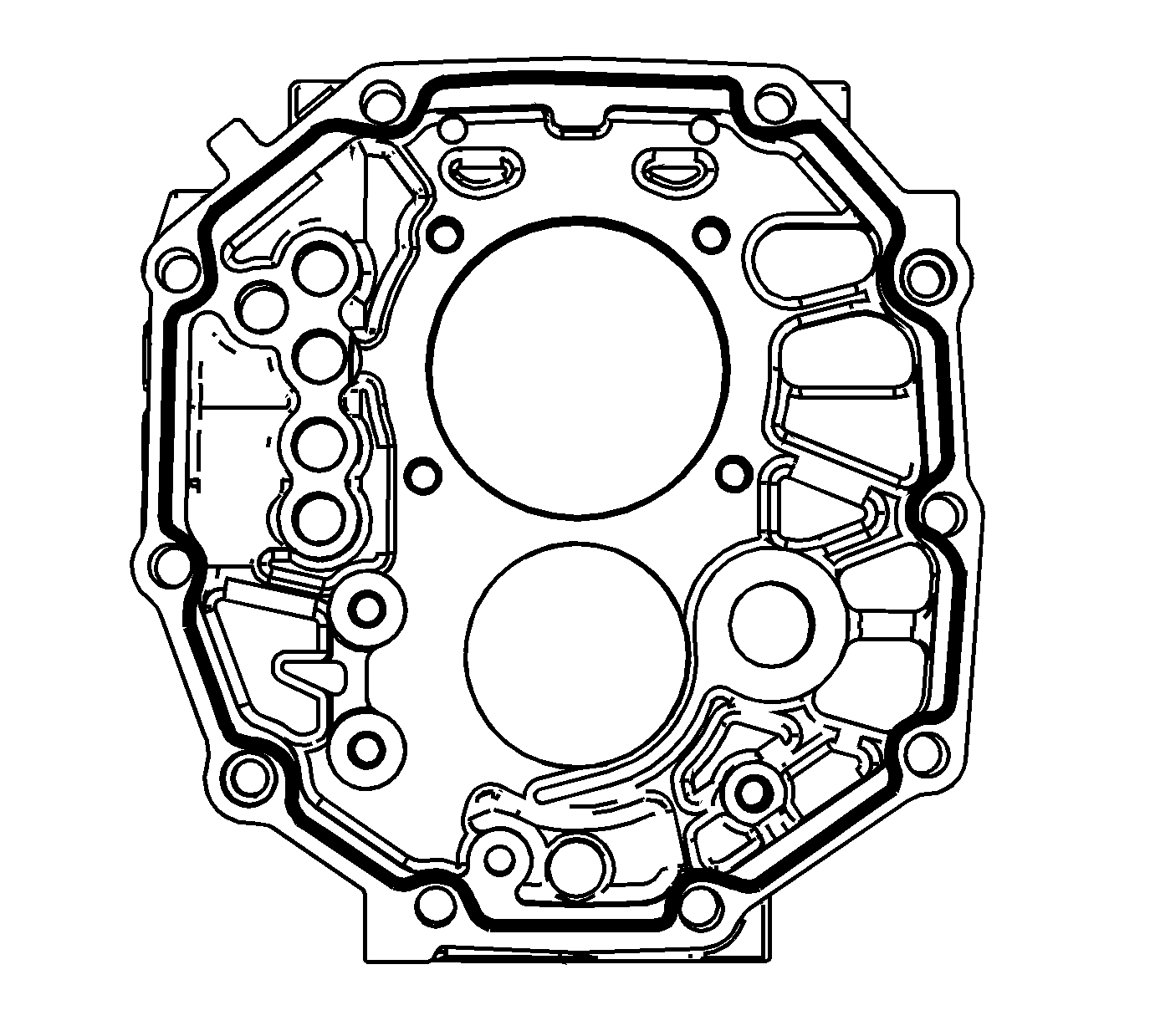
- Apply a 3 mm (1/8 in) bead of sealant GM P/N 89020326 (Canadian P/N 89021188) to the front of the intermediate case.
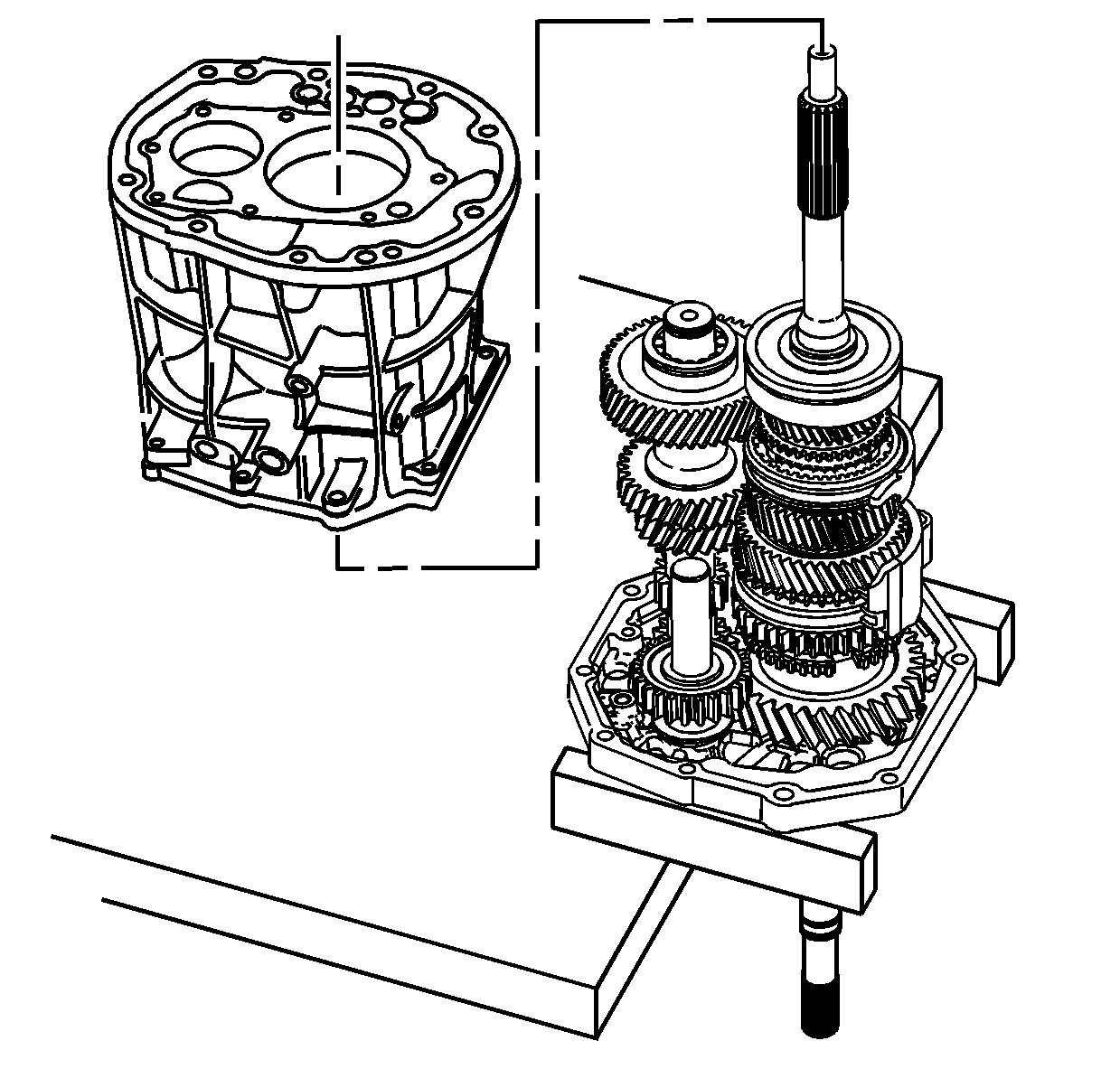
- Support the intermediate case on wooden blocks, with the output shaft over the edge of a workbench, to allow installation of the transmission case.
Note: The 4th blocking ring may have moved out of position. The 4th blocking ring tabs should be seated in the notches of the 3rd/4th synchronizer hub.
- Install the transmission case to the intermediate case.
| • | Ensure the 4th blocking ring is seated properly. |
| • | Ensure the location pins are installed. |
| • | Slide the transmission case over the shift rails. |
| • | Use a soft-face hammer to install the transmission case completely to the intermediate case. |
| • | Do not let the sealer air dry. |
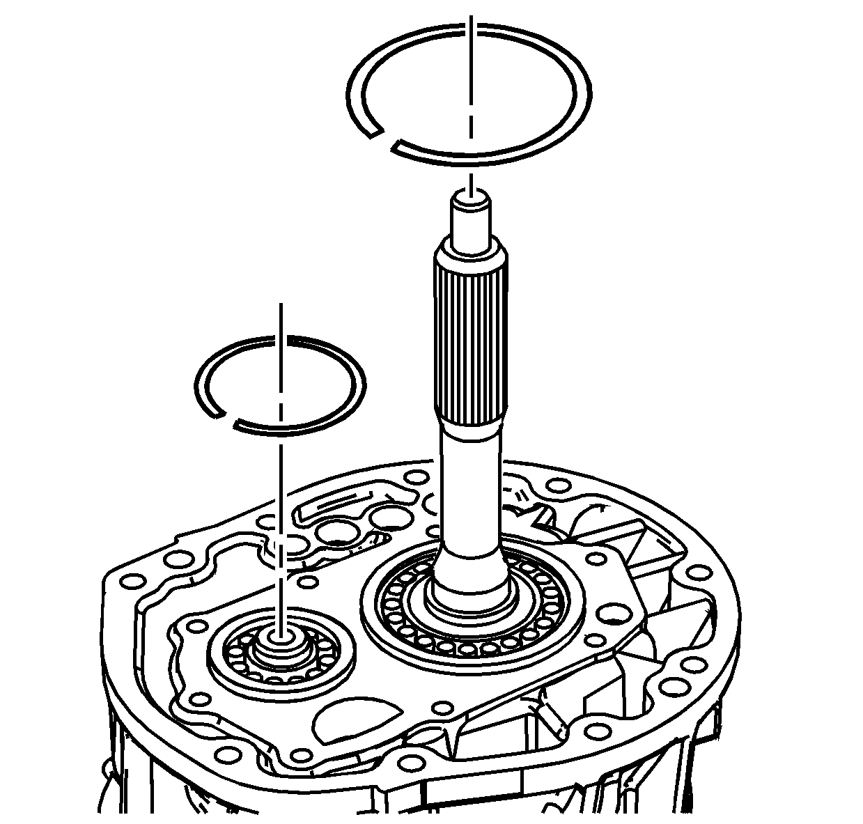
- Install the countershaft front bearing outer retaining ring. It may be necessary to lift up the countershaft in order to install the retaining ring.
- Install the input shaft bearing outer retaining ring. If the retaining ring will not seat flush to the case, the 4th blocking ring was not in the correct position.
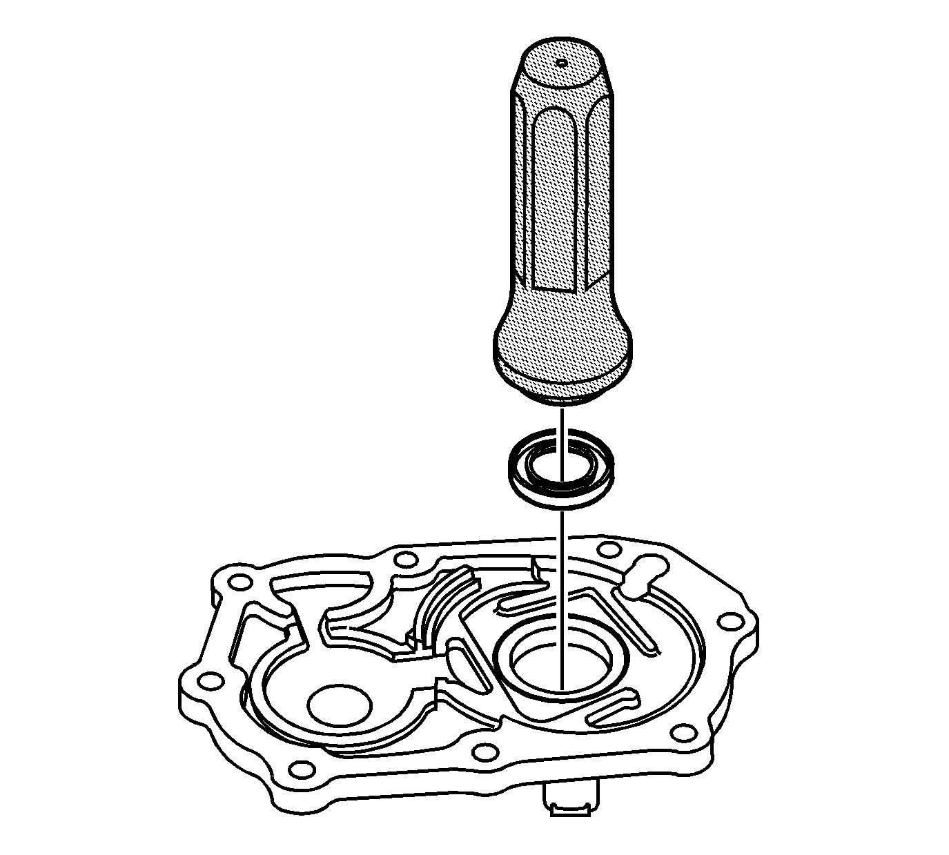
- Using
J 45866 installer
, install a new input shaft seal in the input shaft bearing retainer.
| • | The spring side of the seal goes toward the tool. |
| • | Ensure the seal is installed square. |
| • | The tool will install the seal to the correct depth. |
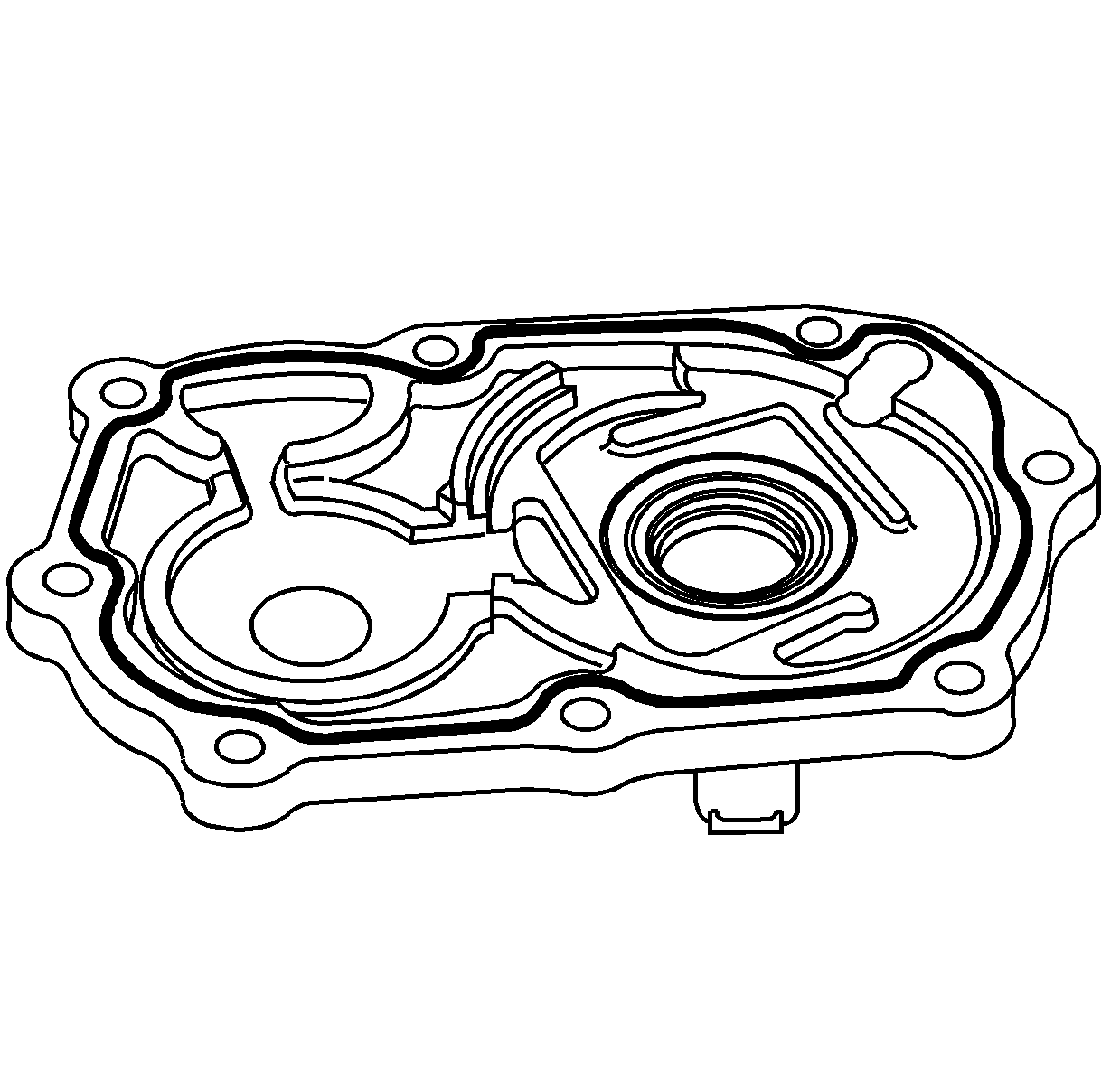
- Apply a 3 mm (1/8 in) bead of sealant GM P/N 89020326 (Canadian P/N 89021188) to the input shaft bearing retainer.
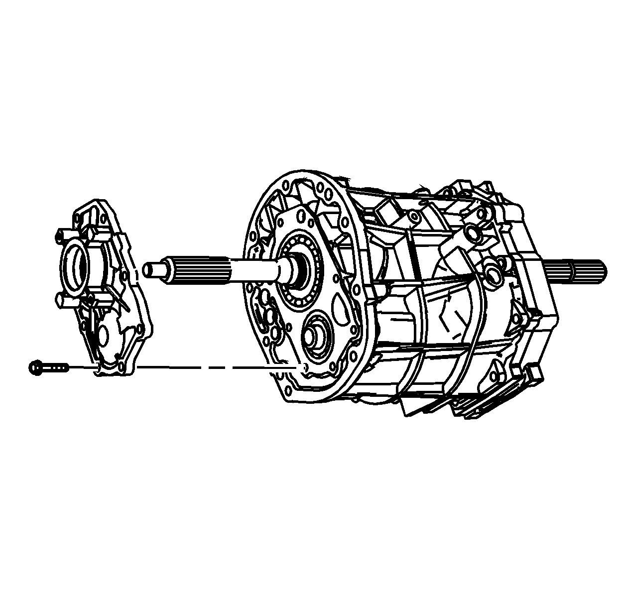
Note: Ensure the seal is not caught on the input shaft.
- Install the input shaft bearing retainer.
Note: The input shaft bearing retainer bolts must not be used again. Always install new retainer bolts.
- Install the bearing retainer bolts and tighten to
17 N·m (12 lb ft).
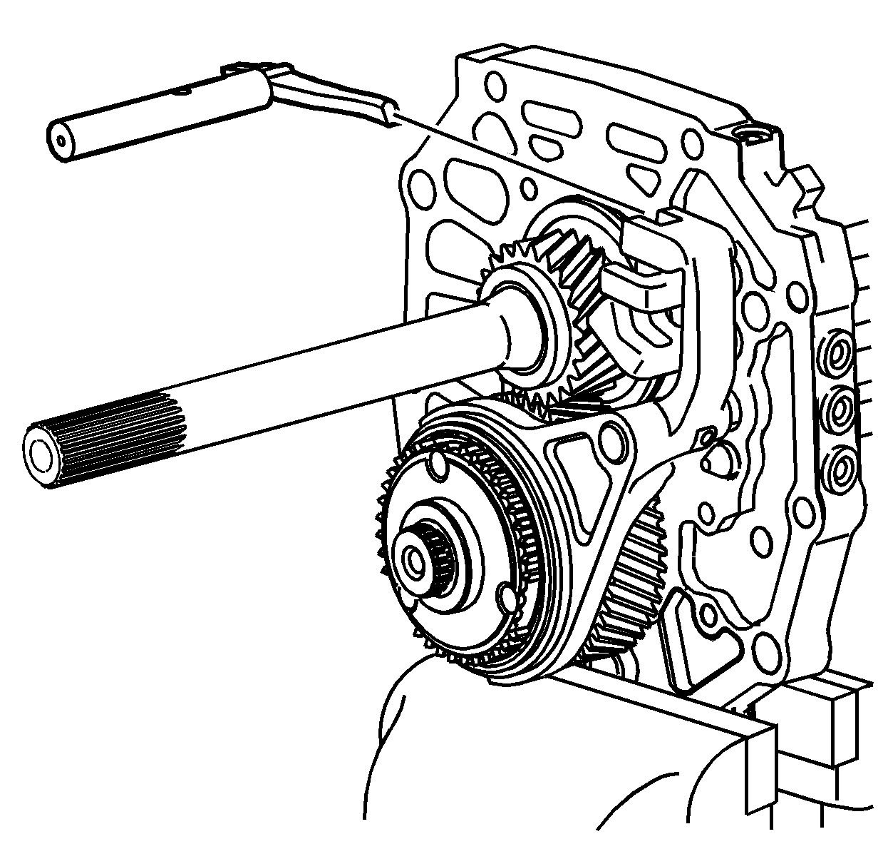
- Install the shift control shaft in the shift shaft gates.
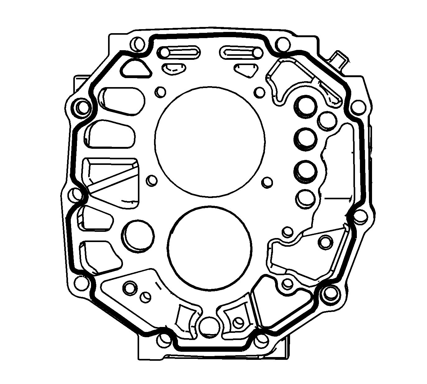
- Apply a 3 mm (1/8 in) bead of sealant GM P/N 89020326 (Canadian P/N 89021188) to the rear of the intermediate case.
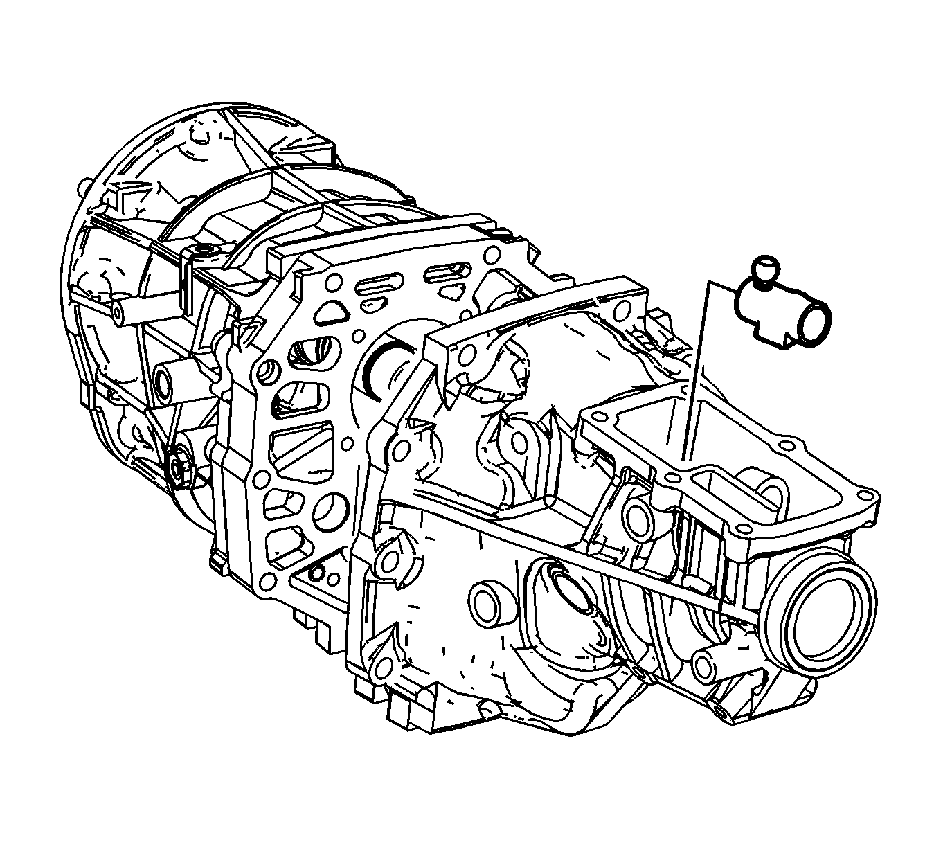
- Install the extension housing to the intermediate case.
| • | Slide the case over the shift control shaft. |
| • | Install the shift control socket on the shift control shaft. |
| • | Ensure the extension housing is installed completely to the intermediate case. |
| • | Use a soft-face hammer to tap the extension housing in place. |
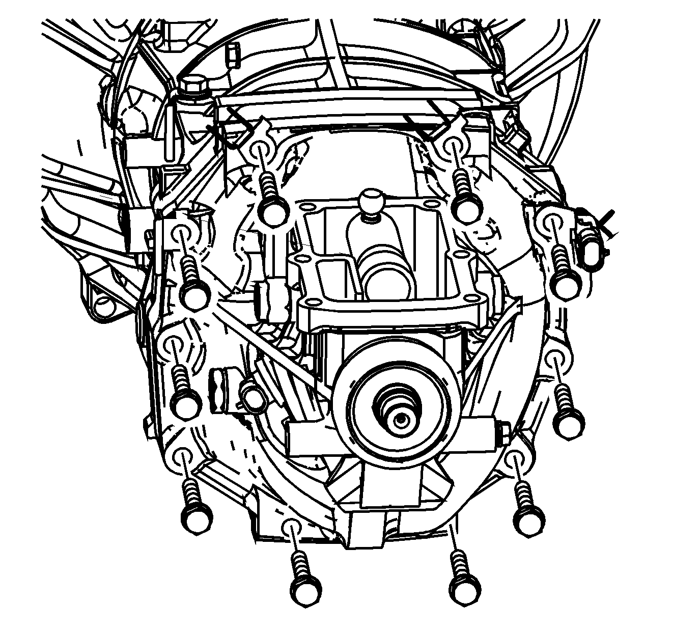
- Install the extension housing retaining bolts and studs, with the brackets, to the proper location as marked during disassembly. Tighten the extension housing bolt and studs to
37 N·m (27 lb ft).
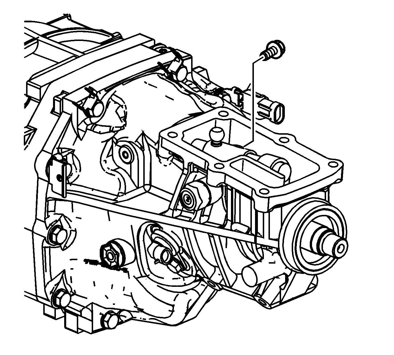
Note: Do not use the shift control lever socket bolt again. Always install a new lever socket bolt.
- Install the control lever bolt and tighten to
33 N·m (24 lb ft).
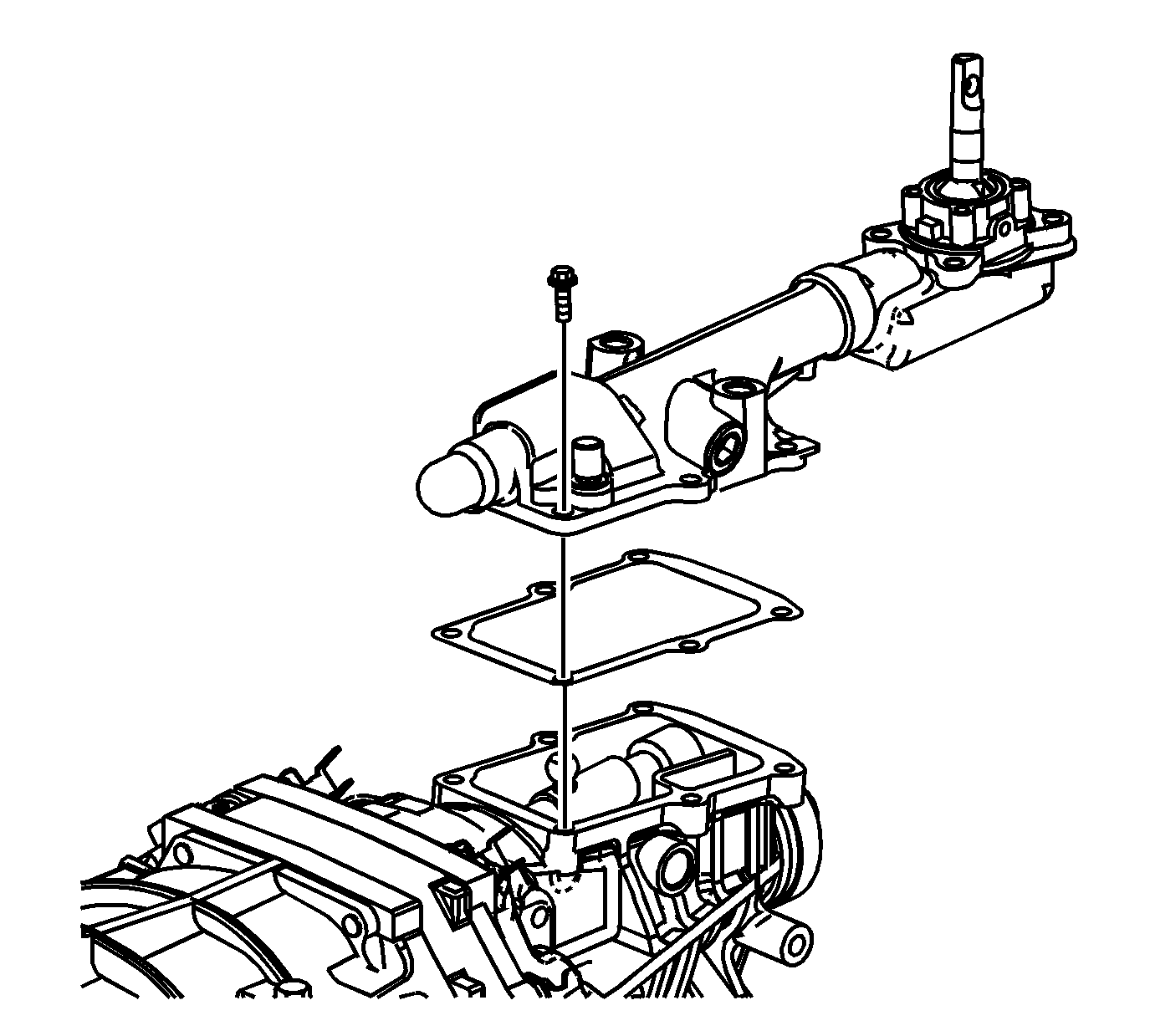
- Install the shift control housing with a NEW gasket.
- Install the shift control housing bolts and tighten to
20 N·m (14 lb ft).
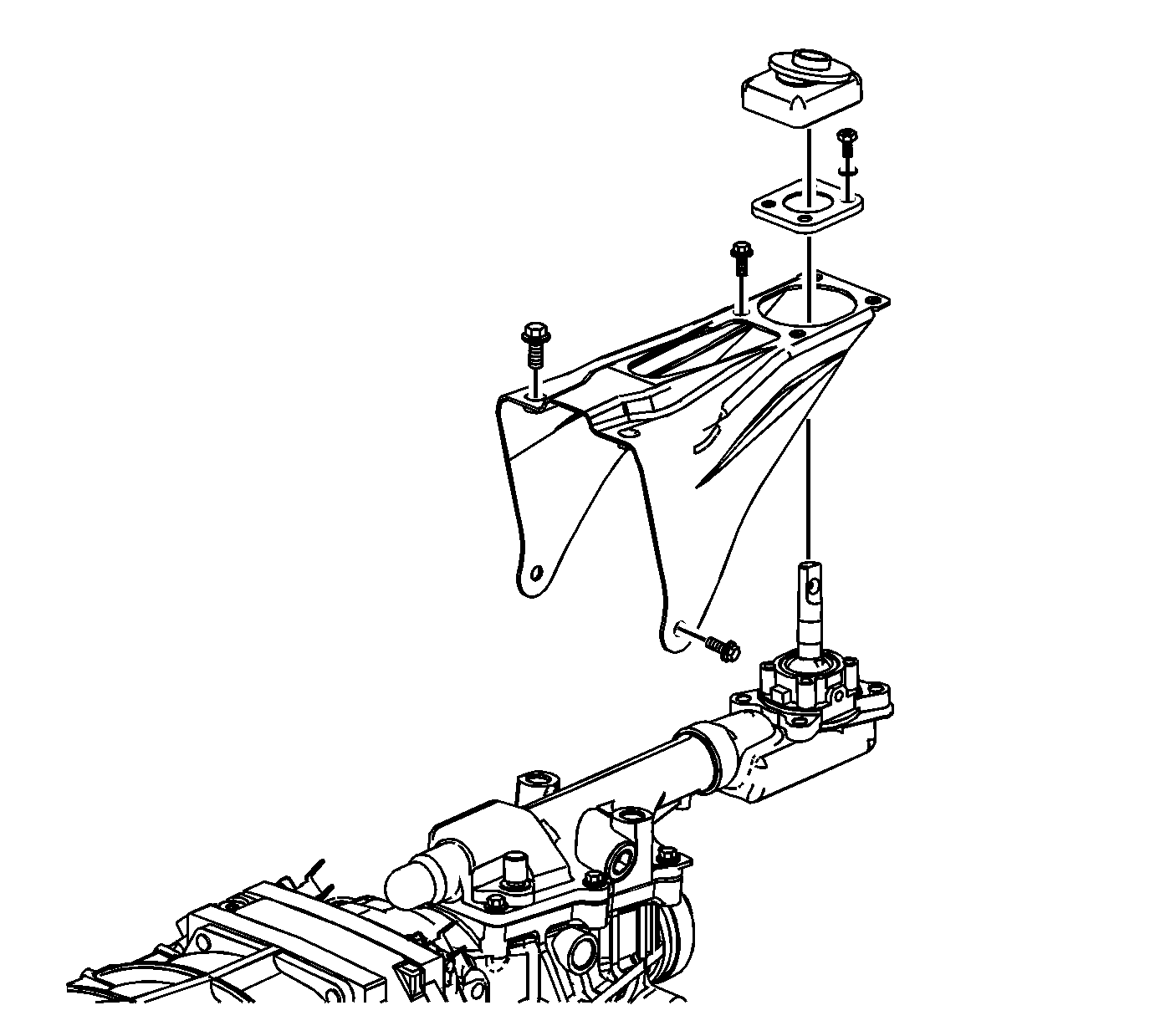
- Install the shift control bracket.
| 77.1. | Tighten the shift control bracket bolts (M10x1.25) to
35 N·m (26 lb ft). |
| 77.2. | Tighten the shift control bracket bolts (M8x1.25) to
20 N·m (15 lb ft). |
- Install the shift control lever bolt/screw and retainer. Tighten the shift control lever bolt/screw to
8 N·m (71 lb in).
- Install the shift control lever boot.
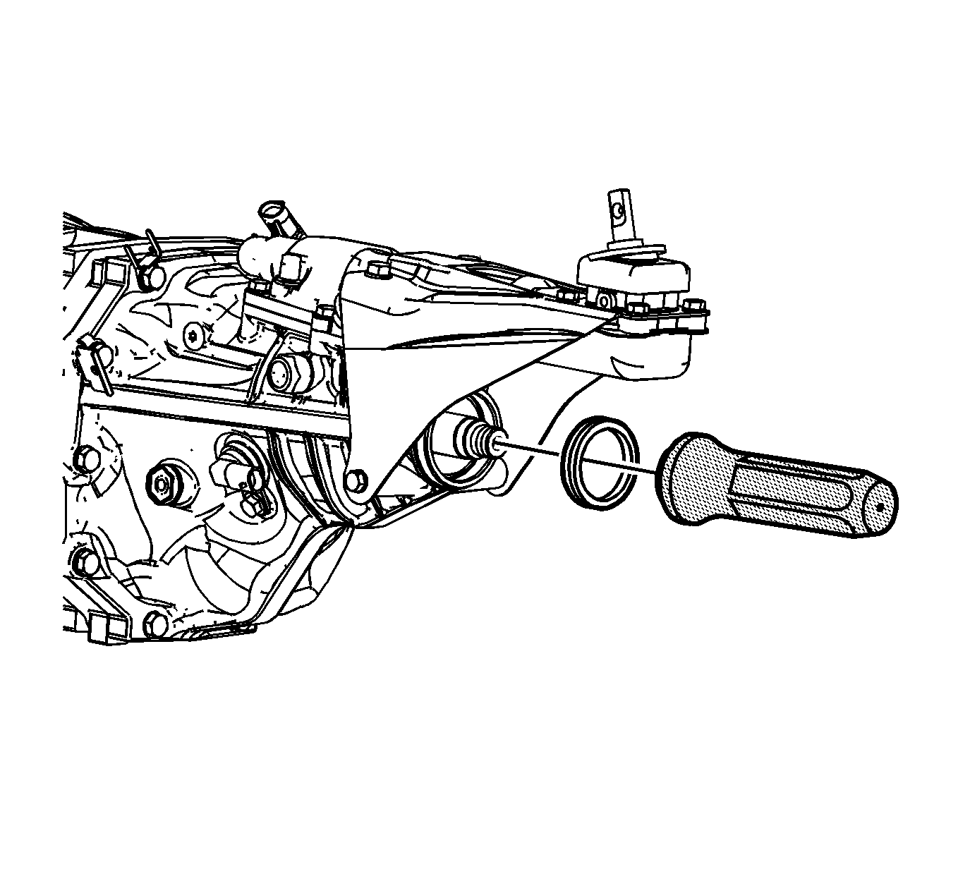
- Using the
J 45868 , install a new output shaft seal.
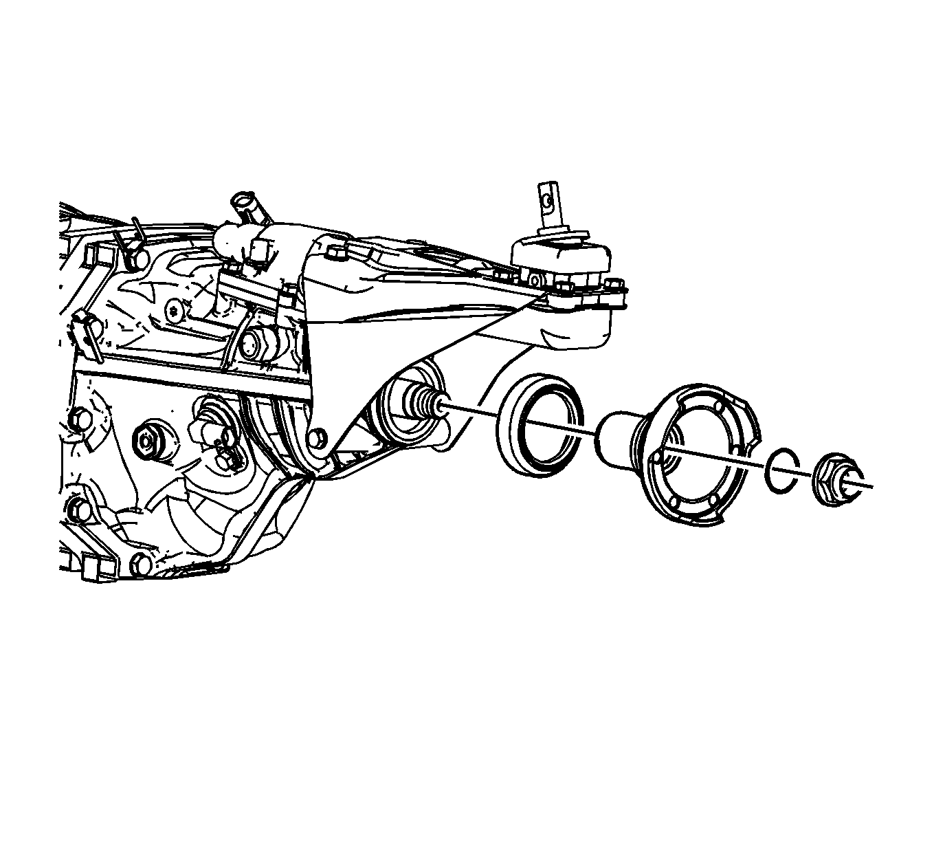
- Install the output flange dirt deflector to the output flange.
- Install the output flange.
- Install the o-ring seal.
- Install the output shaft nut and tighten to
113 N·m (83 lb ft).
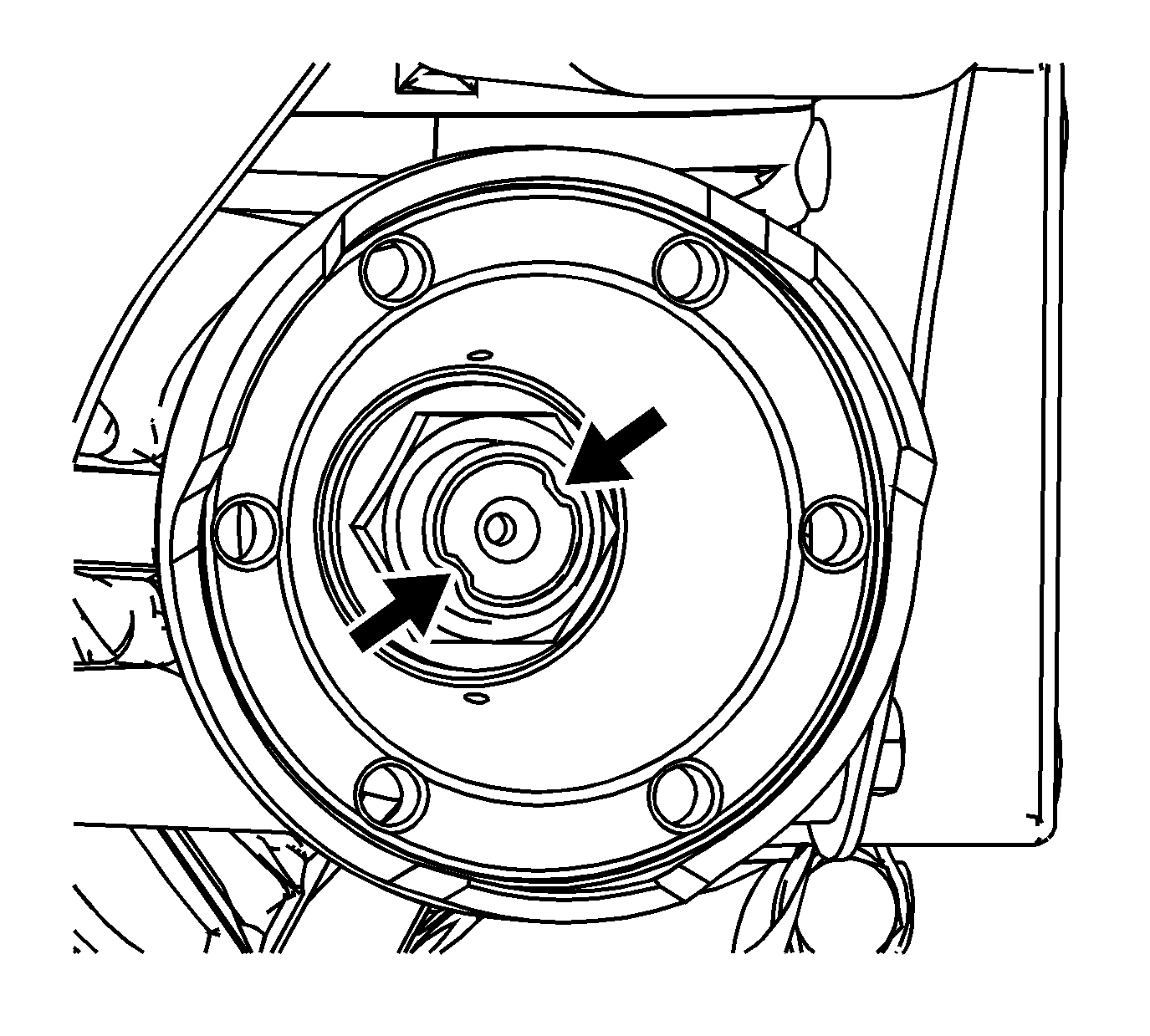
- Use a hammer and a punch to crimp the output shaft nut to the output shaft.
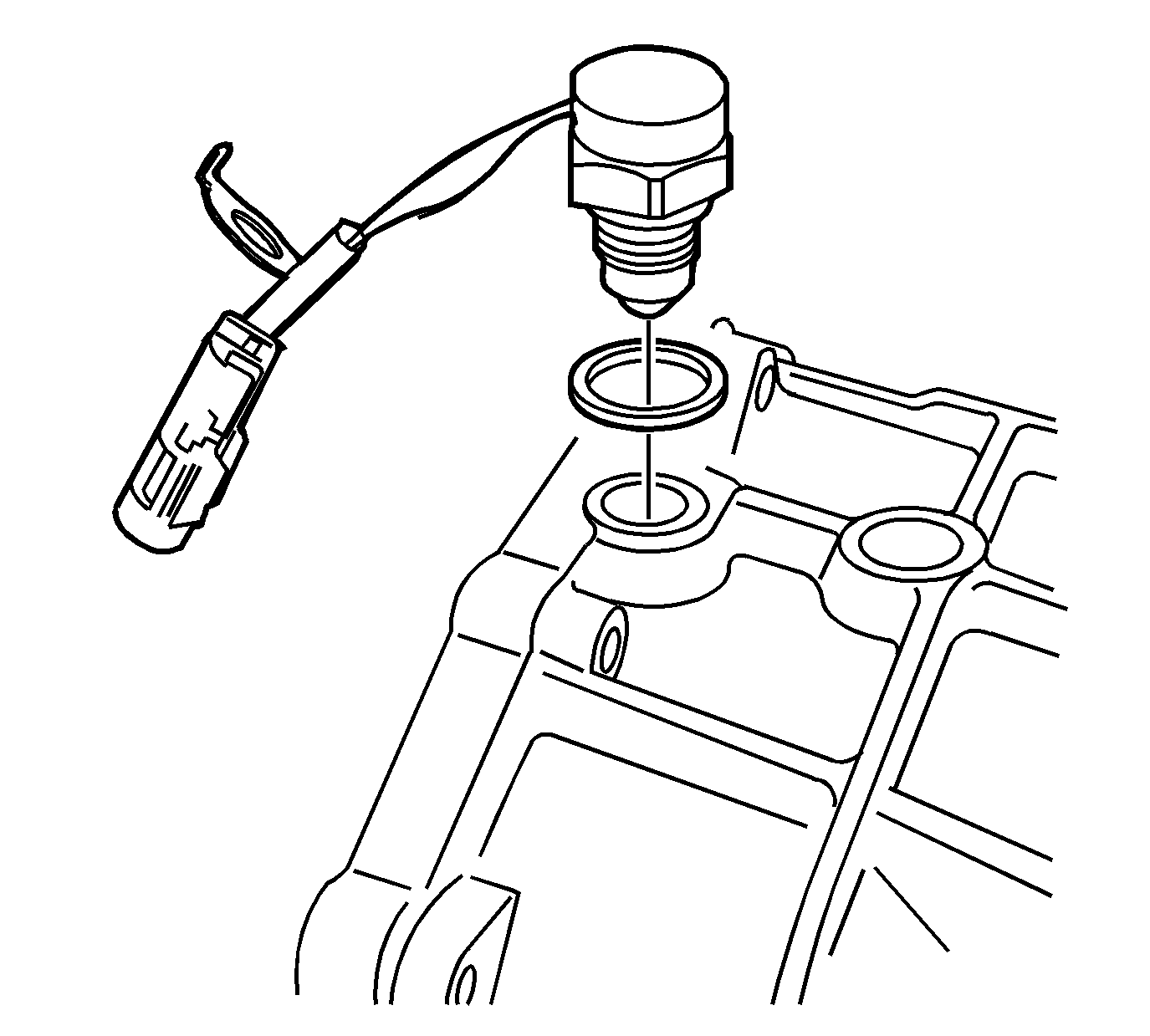
- Install the backup lamp switch, with the aluminum washer, in the front case. Tighten the switch to
44 N·m (32 lb ft).
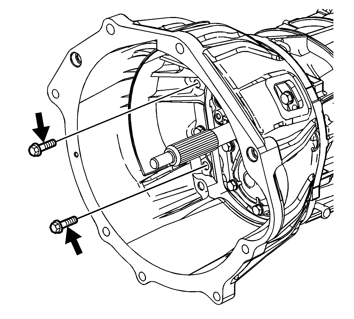
- Using a soft-face hammer to assist, install the clutch housing to the transmission case.
Note: Two of the clutch housing bolts require sealant. If sealant is not used, leakage will occur. Always use new bolts.
- Install the 2 new bolts in the clutch housing location, as shown.
- Install the remaining clutch housing bolts and tighten to
36 N·m (27 lb ft).
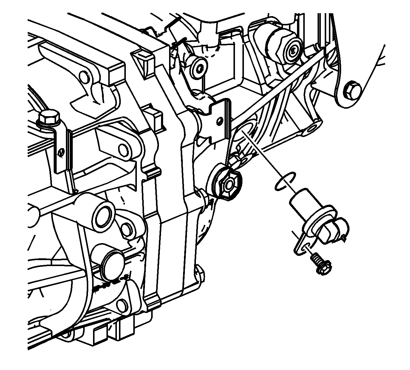
- Install the vehicle speed sensor (VSS) with O-ring seal. Tighten the VSS to
17 N·m (12 lb ft).
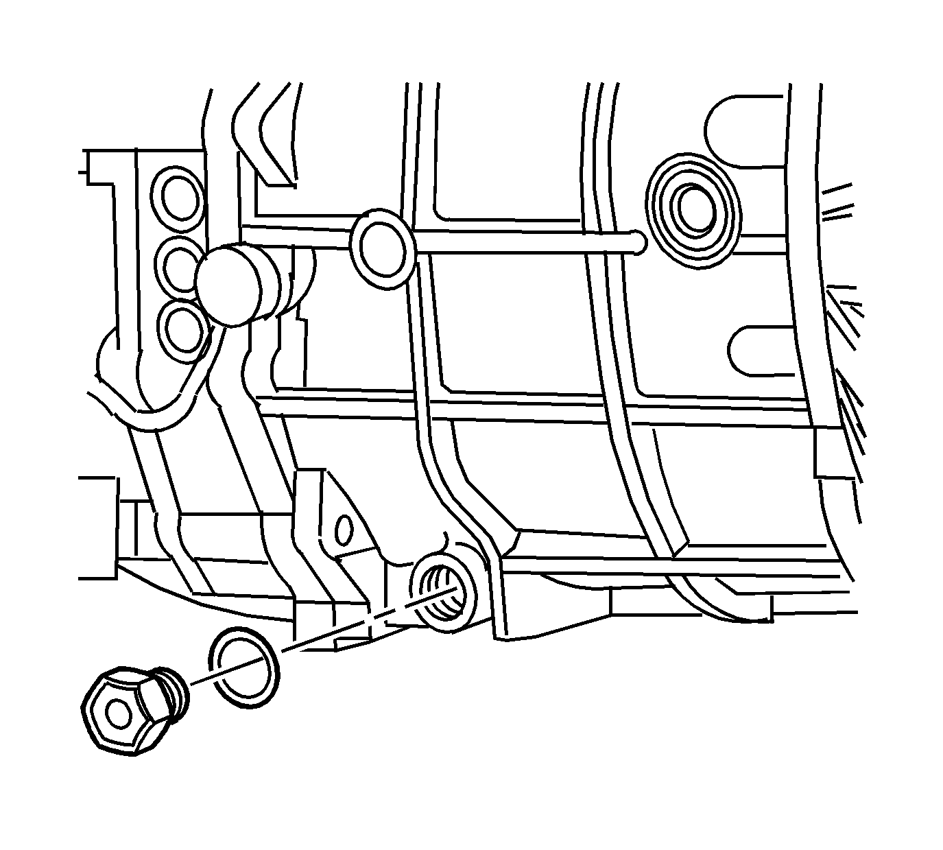
- Install the drain plug with a new gasket and tighten the drain plug to
37 N·m (27 lb ft).


