GM Service Manual Online
For 1990-2009 cars only
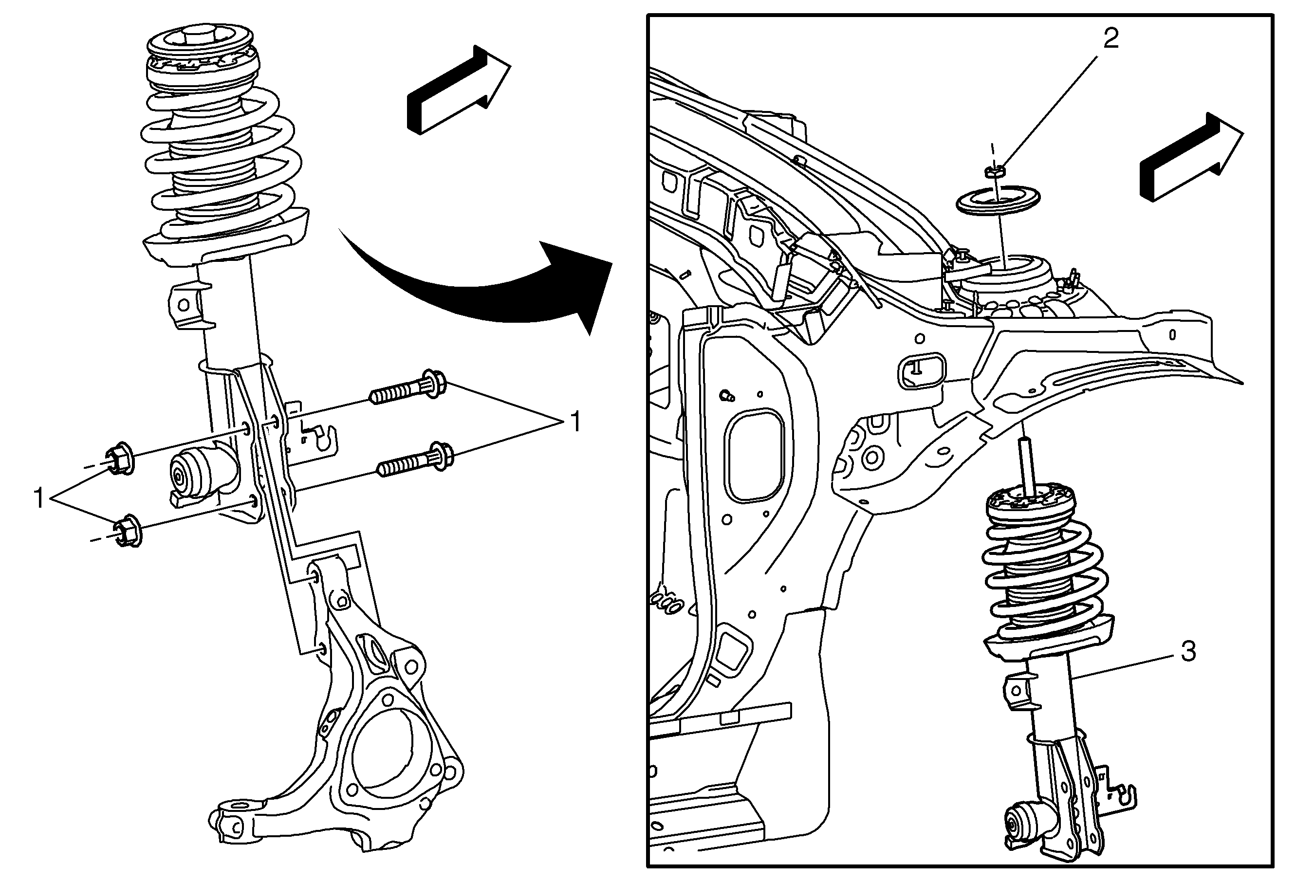
Object Number: 2018658  Size: MF

Callout

Component Name

Preliminary Procedures

  1. Raise and support the vehicle. Refer to Lifting and Jacking the Vehicle.
  2. Remove the tire and wheel assembly. Refer to Tire and Wheel Removal and Installation.
  3. Support the lower control arm, using a suitable jack stand.
  4. Disconnect the wheel speed sensor electrical connector from the front strut, and any other connector if equipped. Refer to Front Wheel Speed Sensor Replacement.
  5. Remove the stabilizer shaft link from the front strut. Refer to Stabilizer Shaft Link Replacement.
  6. Remove brake hose, connector and clip from the strut.

1

Steering Knuckle Bolt/Nut (Qty: 2)

Caution: Refer to Fastener Caution in the Preface section.

Procedure

Install NEW bolts.

Tighten
85 N·m(63 lb ft) + 60 degrees + 15 degrees

2

Upper Strut Fastener

Procedure

Use the CH-8996662 sleeve and CH-49375 wrench to hold the upper fastener.

Tighten
45 N·m(33 lb ft)

Special Tools

    • CH-8996662 Sleeve
    • CH-49375 Wrench

For equivalent regional tools, refer to Special Tools.

3

Strut Assembly

Procedure

For servicing the individual strut components, refer to Strut, Strut Component, and Spring Replacement.