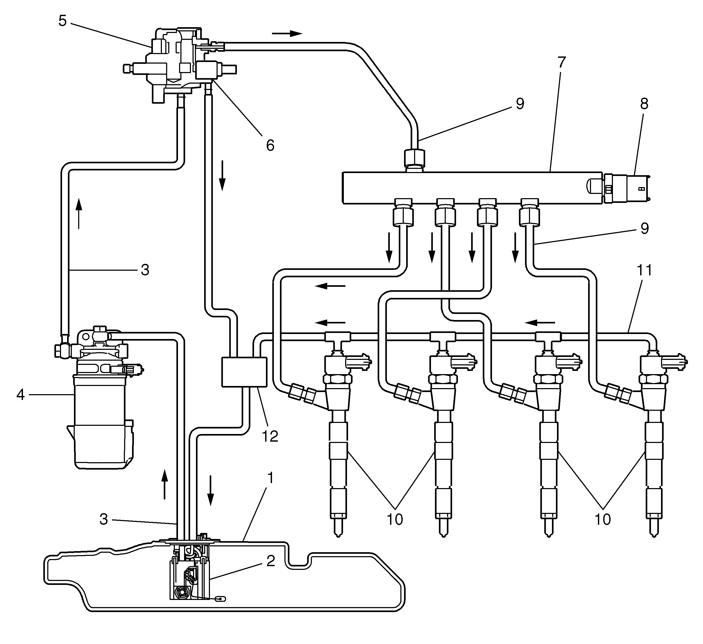
- Fuel tank
- Fuel sender assembly
- Fuel lines
- Fuel filter
- Fuel pressure pump
- Fuel regulator valve
- Fuel rail/reservoir
- Fuel pressure sensor
- High pressure pipe
- Fuel injectors
- Fuel return hoses/pipes
- Return fuel container
The fuel system is of direct injection common rail type. The fuel sender assembly (2), supplies fuel through the fuel feed pipe to the high pressure mechanical fuel injection pump (5). The mechanical fuel injection pump (5) is located on the lower left side of the engine. Fuel is drawn through the fuel filter/heater element housing (4), which combines a water separator, a fuel heater element, and a filter element. The mechanical fuel injection pump output is controlled by the engine control module (ECM), and provides fuel at the pressure needed by the fuel injectors (10). The fuel injectors supply fuel directly to the combustion chambers of the engine. A separate pipe returns unused fuel through the return fuel container (12) to the fuel tank. The mechanical fuel injection pump, fuel rail pressure, fuel injection timing, and injection duration are controlled by the ECM.
Fuel Tank
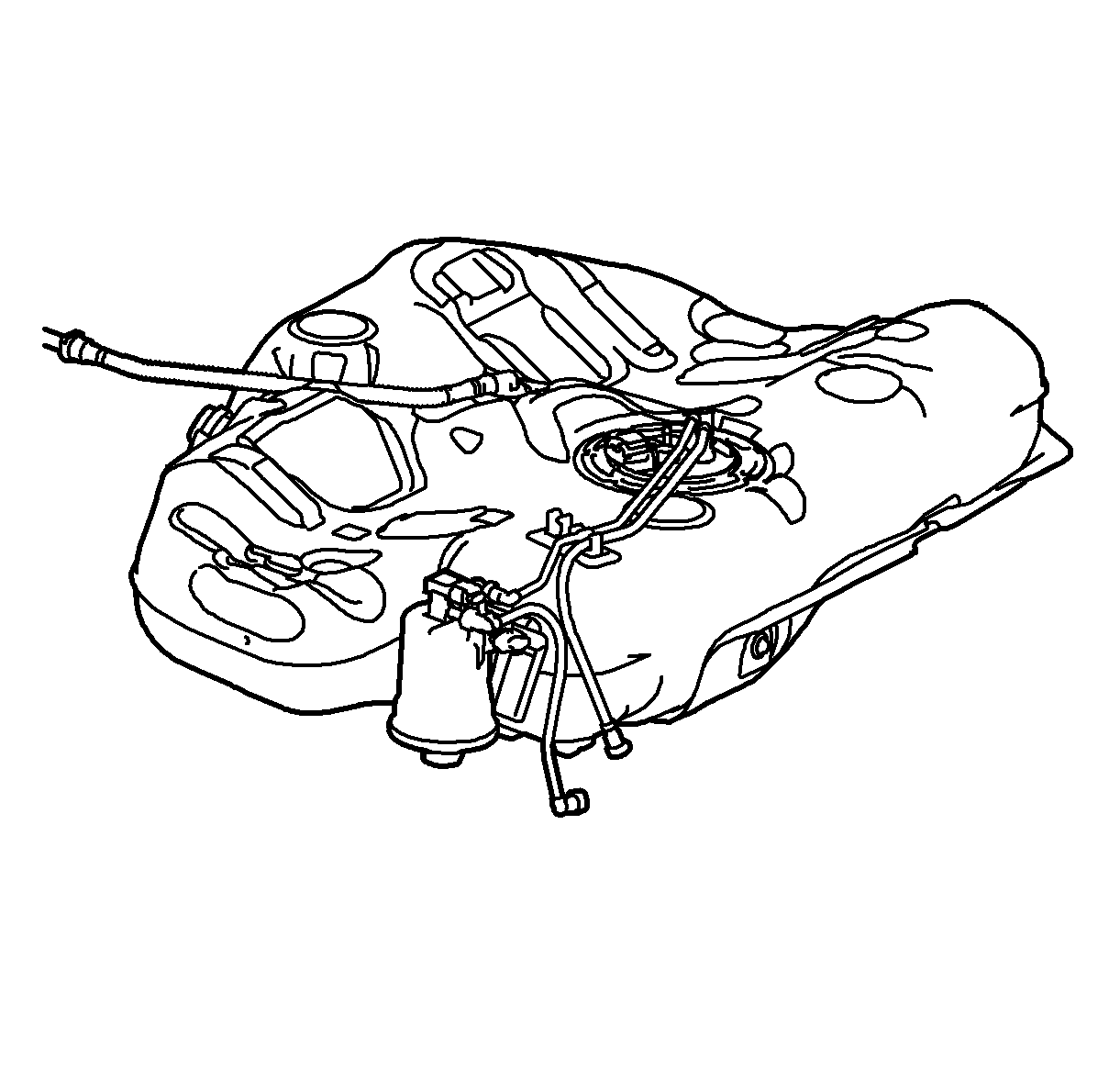
The fuel tank (1) stores the fuel supply. The fuel sender assembly (2) is attached to the primary fuel tank module assembly. The fuel pump supplies fuel to the high pressure mechanical fuel injection pump (5).
The fuel tank is held in place by 2 metal straps that attach to the frame. The fuel tank is molded from high density polyethylene.
Fuel Filler Cap
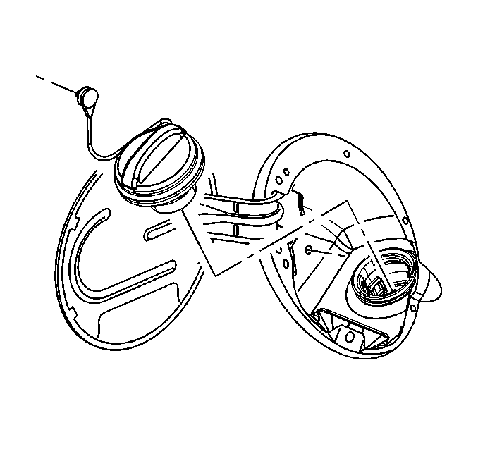
The fuel filler cap has a torque-limiting device that prevents the cap from being over tightened. To install, turn the cap clockwise until you hear audible clicks. This indicates that the cap is fully seated.
Fuel Sender Assembly
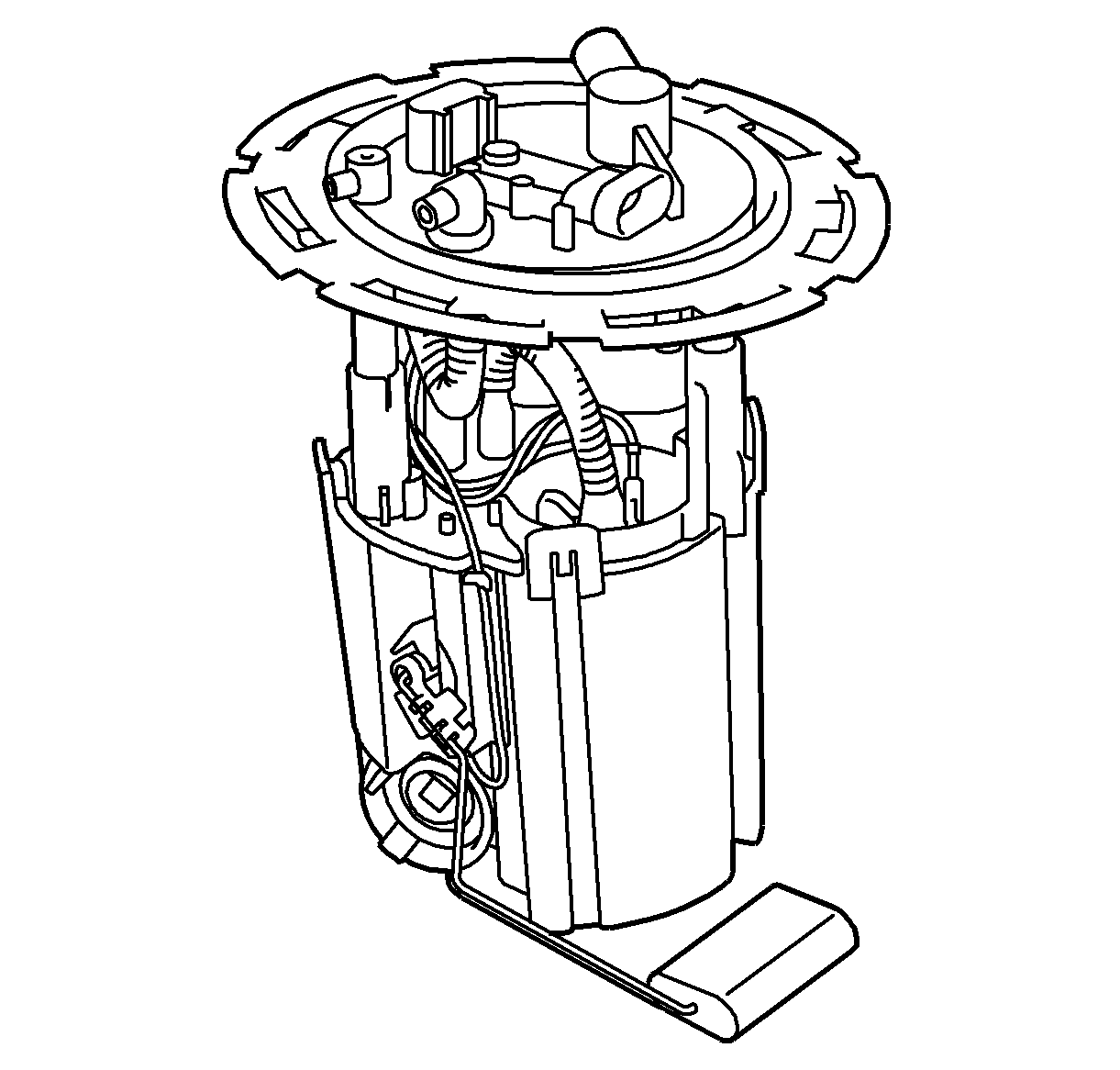
The fuel tank sender assembly (2) is located inside the fuel tank. The fuel tank sender assembly consists of the following major components:
| • | The fuel pump |
| • | The fuel level sensor |
| • | The fuel strainer |
Fuel Level Sensor
The fuel level sensor consists of a float, a wire float arm, and a ceramic resistor card. The position of the float arm indicates the fuel level. The fuel level sensor contains a variable resistor which changes resistance in correspondence with the amount of fuel in the fuel tank. The engine control module (ECM) sends the fuel level information to the instrument panel cluster (IPC). This information is used for the instrument panel (I/P) fuel gage and the low fuel warning indicator as well as for the driver information center (DIC). The ECM also monitors the fuel level input for various diagnostics.
Fuel Strainer
The fuel strainer attaches to the lower end of the fuel sender. The fuel strainer is made of woven plastic. The function of the fuel strainer is to filter contaminants. The fuel strainer is self-cleaning and normally requires no maintenance. Fuel stoppage at this point indicates that the fuel tank contains an abnormal amount of sediment.
Fuel Pump
The fuel pump (2) is mounted in the fuel tank module reservoir. The fuel pump is an electric pump. Fuel is pumped to the mechanical fuel injection pump at a specified flow and pressure (4 bar). The control module controls the electric fuel pump operation through a fuel pump relay.
Fuel Pressure Pump
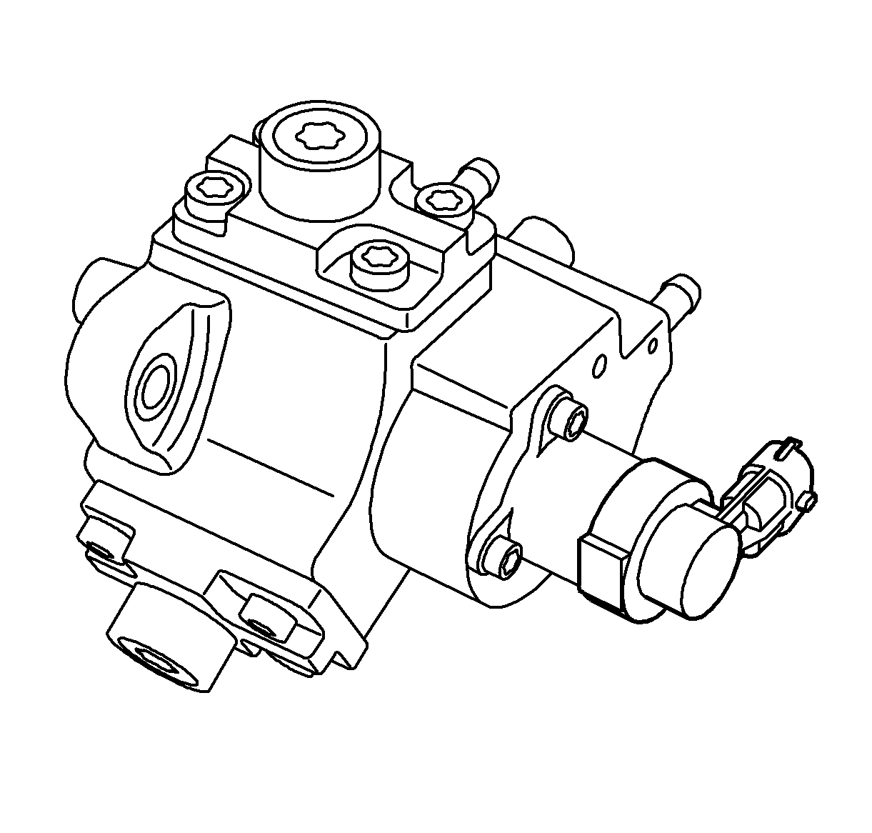
The three-cylinder high-pressure pump (5) delivers the injection pressure, which can be up to 160 MPa (1600 bar). As the engine's fuel requirements vary over a wide range, the fuel pressure that is supplied by the high-pressure pump to the fuel rail must be regulated. This is done with the fuel regulator valve (6).
Fuel Regulator Valve
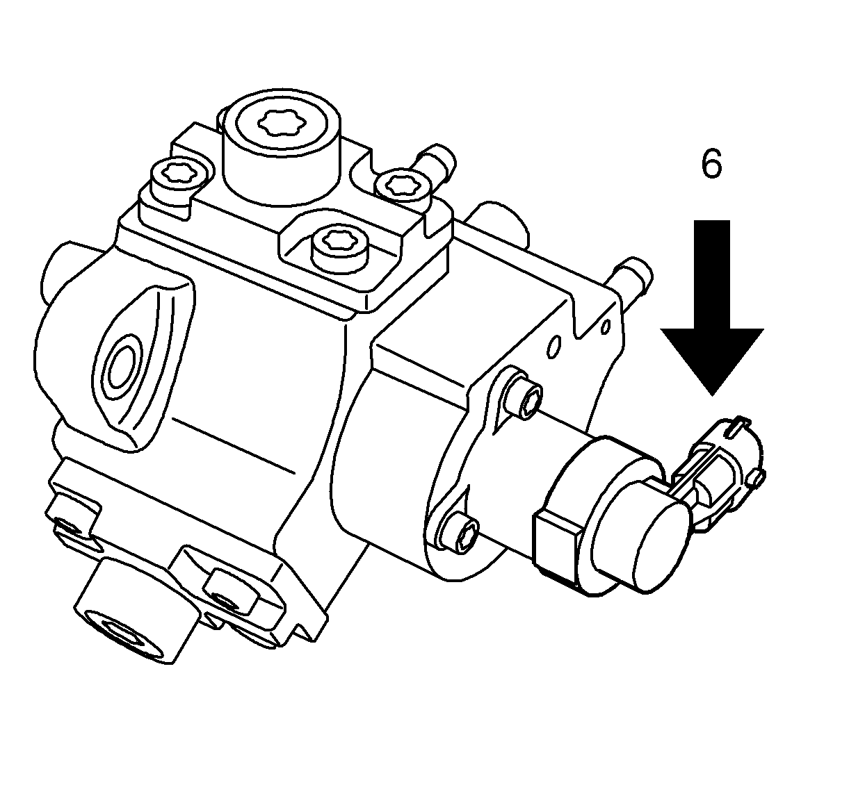
The fuel regulator valve (6) on the high-pressure pump (5) is used to restrict the fuel supply to the inlet side of the pump. If fuel requirement is low, the pump supply is restricted so that the cylinders are not completely filled. The pump capacity is regulated, which means its power requirement drops. The high-pressure pump is driven by the camshaft drive and has a given ratio to the crankshaft.
In this way, the high pressure pump can be prevented from running "flat out" (with full pump chamber) when fuel requirements are low. ECM controls the valve and measures the result in the form of attained fuel pressure in the fuel rail. If necessary, the PWM signal to attain requested pressure will be corrected.
Fuel Filter
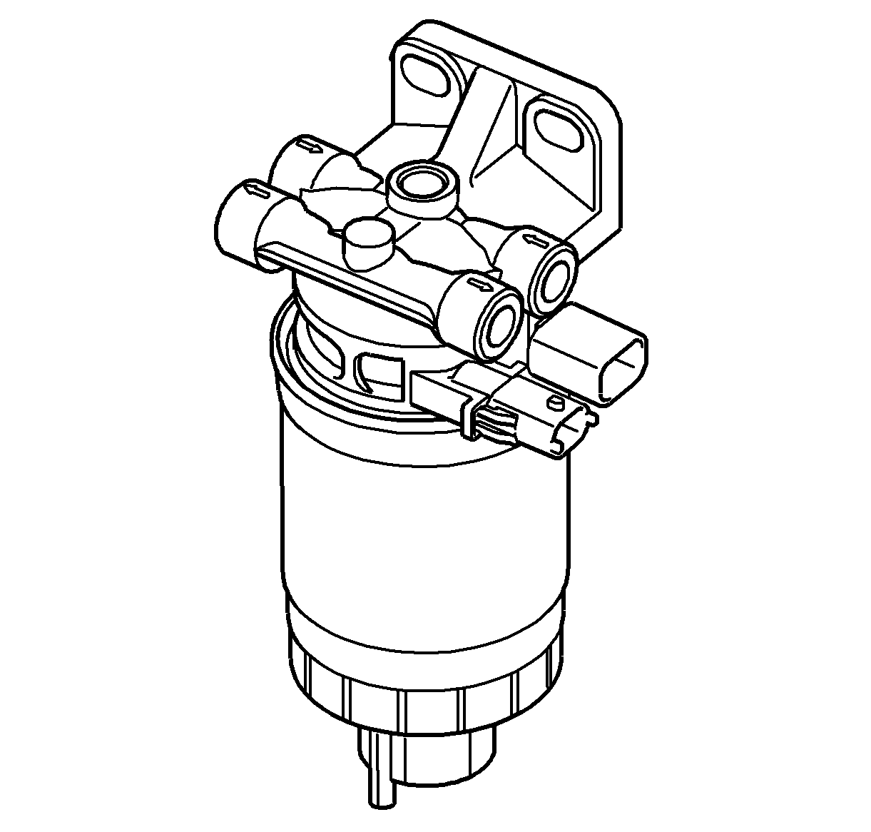
The main task of the fuel filter assembly (4) is to prevent particles of dirt from entering the fuel system. The pore size of the filter compound is 3-5 micrometers. In the filter is also a sensor for detecting whether there is any water in the fuel. The filter holder also contains a preheater element and sensor for the fuel temperature. ECM reads the fuel temperature value and controls the current to the preheater.
Fuel Feed and Return Pipes
The fuel feed pipe carries fuel from the fuel filter assembly on the fuel tank to the high pressure pump. The fuel return pipe (11) carries fuel from the fuel rail assemblies (7) back to the fuel tank via the return fuel container (12). The fuel pipes consist of 2 sections:
| • | The rear fuel pipe assemblies are located from the top of the fuel tank to the chassis fuel pipes. The rear fuel pipes are constructed of steel with sections of rubber hose covered with braiding. · |
| • | The chassis fuel pipes are located under the vehicle and connect the rear fuel pipes to the fuel rail pipes. These pipes are constructed of steel with sections of rubber hose covered with braiding. |
Quick-Connect Fittings
Quick-connect fittings provide a simplified means of installing and connecting fuel system components. The fittings consist of a unique female connector and a compatible male pipe end. O-rings, located inside the female connector, provide the fuel seal. Integral locking tabs inside the female connector hold the fittings together.
Fuel Pipe O-Rings
O-rings seal the connections in the fuel system. Fuel system O-ring seals are made of special material. Service the O-ring seals with the correct service part.
Fuel Rail Assembly
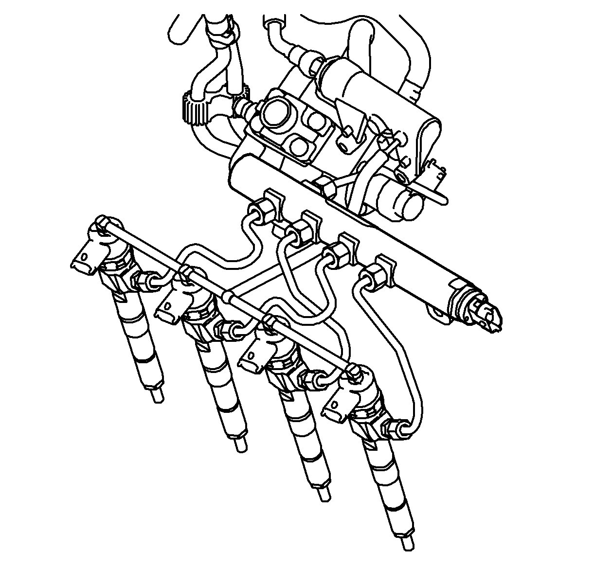
The fuel rail assembly (7) attaches to the cylinder head. The fuel rail assembly distributes pressurized fuel to the fuel injectors (10) through the fuel lines and to act as a reservoir to reduce pulsation in the fuel pressure. A fuel rail pressure sensor (8) is mounted on one of the ends of the fuel rail.
The fuel rail pressure sensor gives (ECM) an indication of fuel pressure. ECM uses this information to regulate fuel pressure, by commanding the fuel pressure regulator valve open or closed on the inlet of the fuel injection pump.
Fuel Injectors and Return Lines
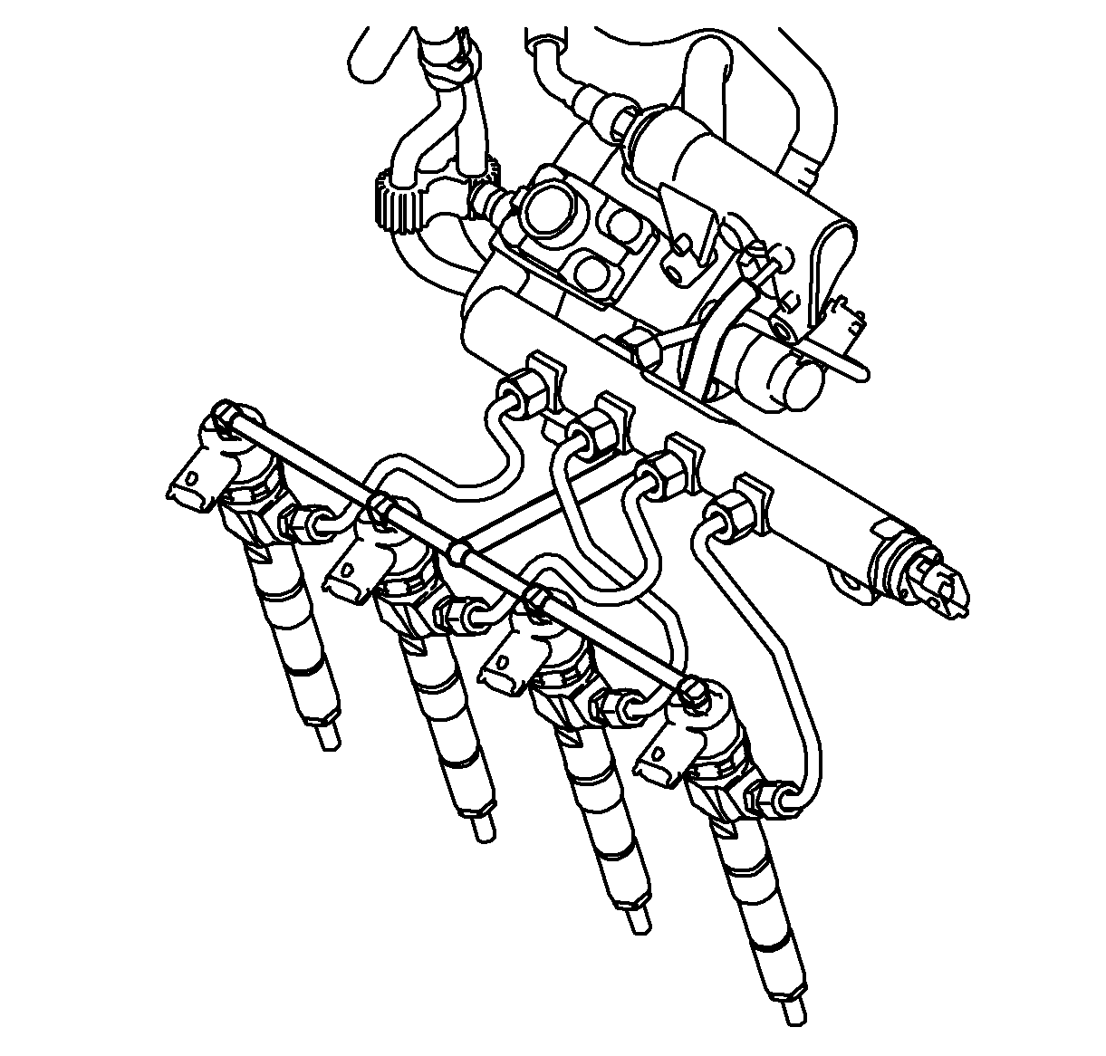
The injectors are low-ohmic solenoid devices, controlled by the ECM, which meters pressurized fuel to a single engine cylinder. The injectors are controlled according to the peak and hold principle. This means that an opening pulse is sent first with a rather high current (peak) in order to obtain a rapid response from the injector. After a certain period of time, the nozzle is assumed to be open and the current will be limited by ECM (hold). ECM can inject fuel up to five times per working stroke with a maximum injection timing of around 1 ms.
The holes through which the fuel is injected must be very small so that the fuel will atomize into small drops. Certain manufacturing tolerances are just a few thousandths of a millimeter. Consequently, it is essential that dirt does not enter the fuel system.
The hoses are used to handle the return fuel from the injectors. Fuel pressure is released from above the fuel injector pintle. The difference in fuel pressure above and below the pintle causes the pintle to open. A controlled leakage occurs in the injectors and passes back to the fuel tank via the fuel return hoses, return fuel container and then to the return fuel line.
