General

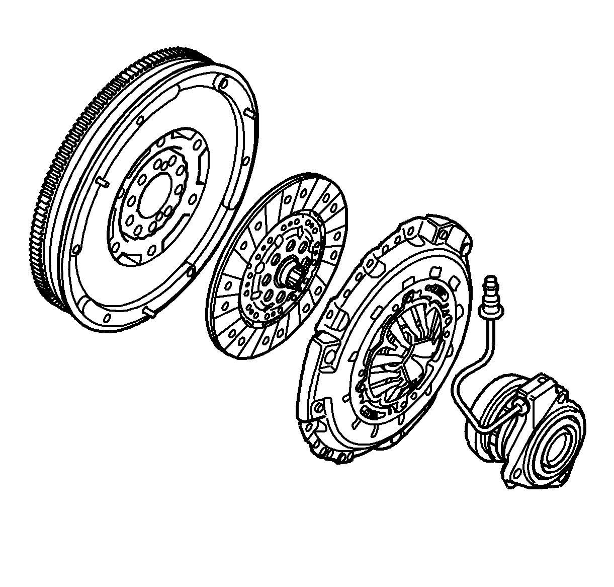
Power is transmitted from the flywheel on the engine to the input shaft in the gearbox via a driven plate. This power is transmitted by the pressure plate, which is bolted to the flywheel, forcing the friction surface of the driven plate against the flywheel.

The driven plate is joined to the primary shaft with a splined joint. When the release bearing on the slave cylinder presses on the "fingers" of the diaphragm spring, the fingers will act like levers to release the clamping force of the pressure plate from the driven plate-flywheel. The engine is disengaged from the transmission in this way.
Clutch with Dual-Mass Flywheel

The ability of modern, high-performance, low-weight engines to absorb vibrations themselves is poor. To reduce noise and improve ride comfort, a dual-mass flywheel has been introduced on some models.
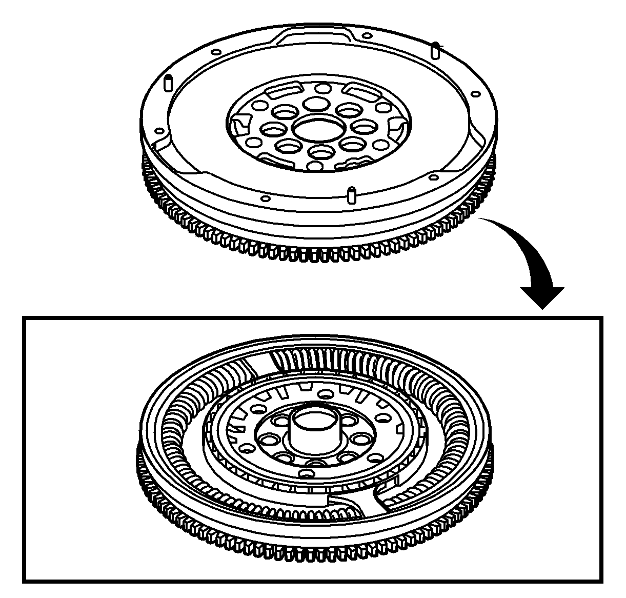
A dual-mass flywheel comprises two separate flywheel masses; a primary and a secondary mass with a spring damper system connecting the two. This almost fully eliminates torsional vibrations in the gearbox and transmission.
The primary section of the dual-mass flywheel is attached to the engine and the secondary mass on the transmission side. These two masses are elastically attached with a spring assembly that absorbs torsional vibrations from the engine.
Wide fluctuations of torque are above all produced during gear changes under load at lower engine speeds, when driving at very low engine speeds when high torque is required and when the engine is started and stopped. These torque peaks are absorbed by the arched springs. At high speeds, the springs are pressed out against the spring housing, reducing their flexation. On the other hand, at how speeds, variations in torque are small, reducing the significance of the outer springs.
Dual-mass flywheels do not have the springs that are normally fitted in the centre of the clutch plate, as the flywheel itself has taken over their role.

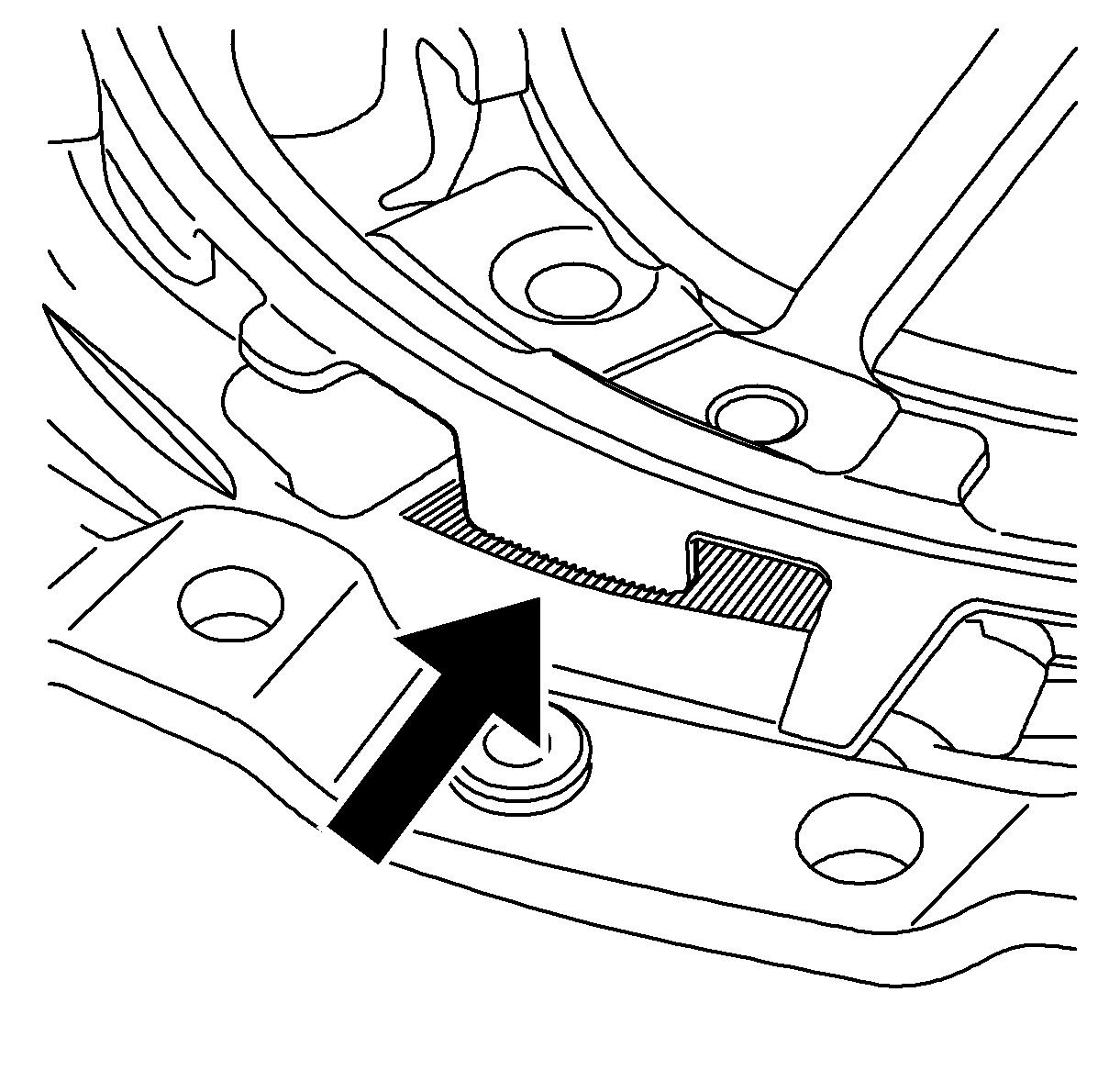
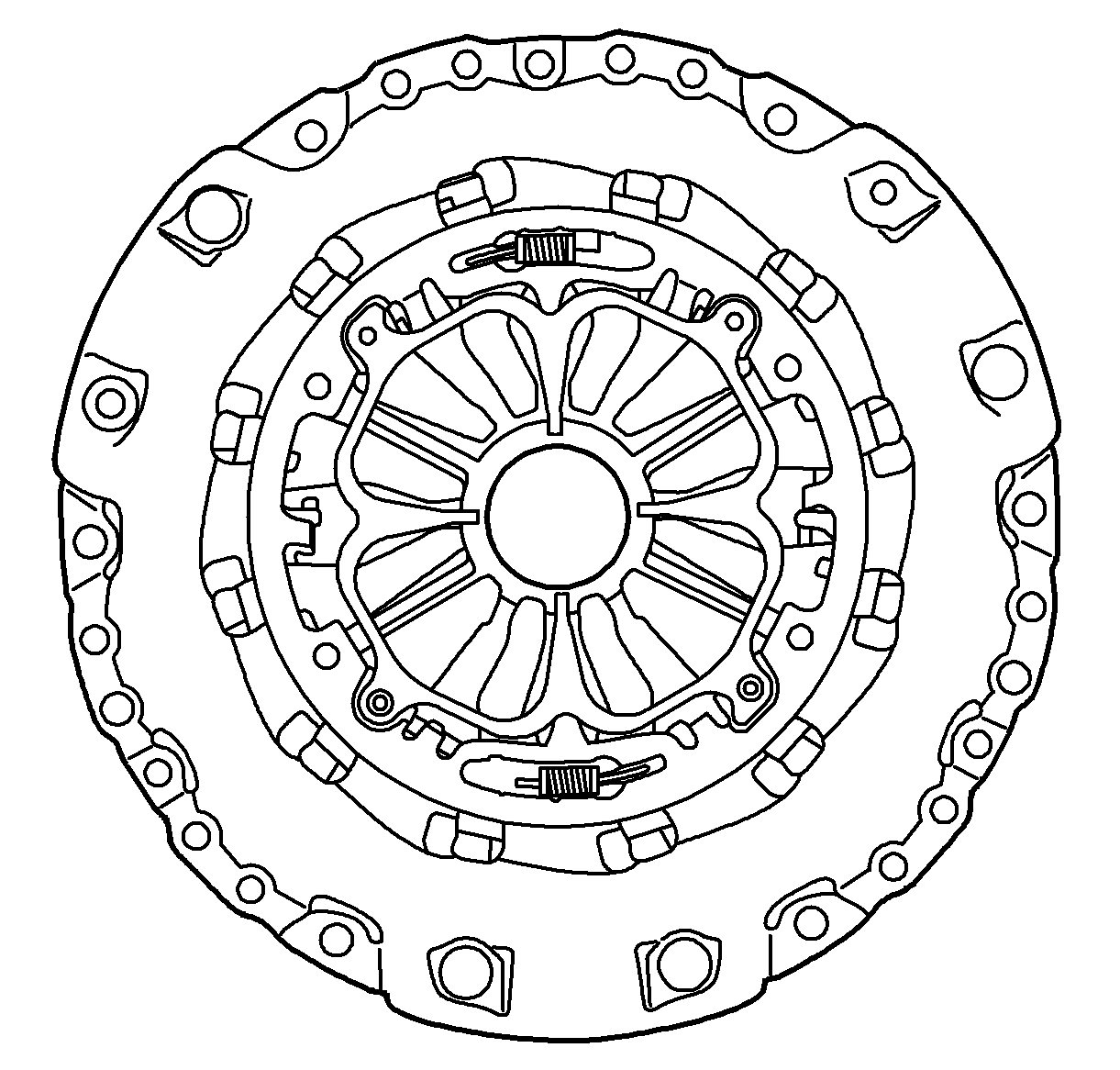
The pressure plate is fully self-adjusting, which means that the compression springs acted on by the release bearing are always in the same position relative to the release bearing. The diaphragm spring can move between an adjustment ring and a wear ring.
When the clutch lining wears, the wear ring moves with the pressure surface of the pressure plate. This movement reduces the load on the adjustment ring, which is rotated by two small springs and locked in position by a catch in the pressure plate housing. This means that the diaphragm spring maintains its original position.
When replacing a dual-mass flywheel both the pressure plate and clutch plate centre should be changed as a unit.
