Headlamp Aiming Adjustment for Travel Abroad
Note: This method of setting headlamps is only intended for short-term use.
Vehicles with adaptive forward lighting
- Pull and hold the signal stalk switch.
- Switch on the ignition.
- After about 3 seconds, a signal sounds. Following this, you can release the signal stalk switch. Then, the AFL control indicator flashes for about 4 seconds after the instrument lamp test.
Note: If the Tourist mode is activated, the AFL indicator lamp flashes for 4 seconds every time the ignition is switched on following the instrument lamp test.
To restore the original setting, repeat the procedure: pull and hold the signal stalk switch, switch on the ignition and wait for the audible signal. The AFL control indicator then stops flashing.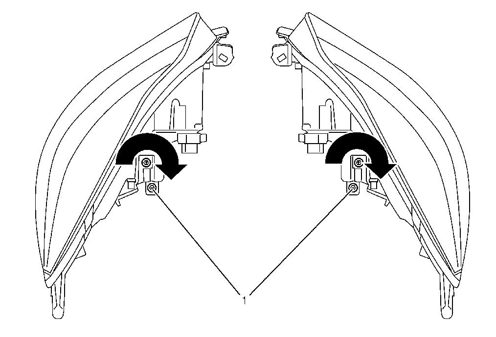
For vehicles with halogen headlamps
Turn adjusting screw (1) on both headlamps 1.5 turns in direction of arrow.
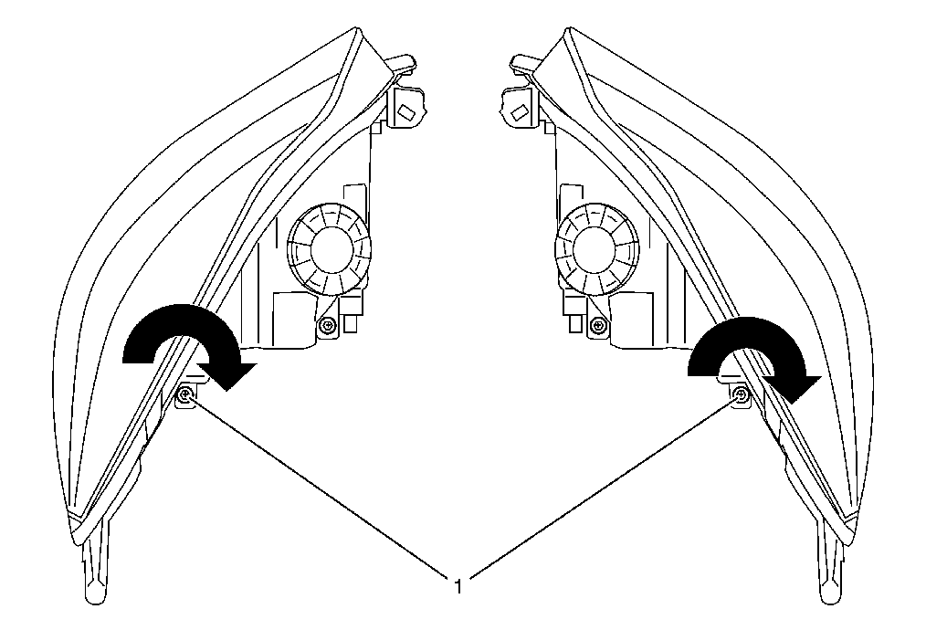
For vehicles with Bi-Xenon headlamps
Turn adjusting screw (1) on both headlamps 2 turns in direction of arrow.
Headlamp Aiming Check and Adjust
76/756 EEC or ECE-R48 guidelines cover checking and adjustment of headlamps on vehicle. Correct adjustment of headlamps on vehicle should enable optimal road illumination by low beam, with minimal dazzling of oncoming traffic. To this end, inclination of headlamp beam to level road surface and angle of beam to vertical longitudinal plane running through vehicle's centre must satisfy conditions laid down in guidelines.
Dazzling (low beam) is considered eliminated if intensity of illumination at a distance of 25 m (82 ft) from each individual headlamp on the plane perpendicular to the road and at height of headlamp as well as beyond, is not greater than 1 lux. This requirement is generally satisfied if headlamp adjustment is carried out according to adjustment guidelines.
Main headlamp housing or retainer displays reference 1.0 % for low beam adjustment according to EEC 76/756 or ECE-R48 guidelines.
Reference 1.0 % corresponds to the adjustment dimension of the headlamp with reference to the inclination of the light beam. The inclination at a distance of 10 m (33 ft) from vehicle headlamp is therefore 10 cm (4 in) (illustrations 2019511 and 2019512). The inclination of the dipped beam headlamp is indicated by its light/dark boundary.
The adjustment guideline is clarified by illustrations 2019511 and 2019512.
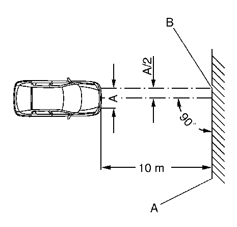
Abbreviations used:
A = Horizontal distance between headlamp centres
B = Central marking
C = Test surface
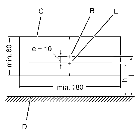
D = Road surface
E = Break point
E = Adjustment dimension in cm, e = H - h (adjustment dimension, main headlamps 1.0 %, e = 10 cm (4 in), front fog lamps 2 %, e = 20 cm (8 in))
H = Height of centre of headlamp over road surface
h = Height of light / dark boundary line of dipped beam above road surface
The headlamp adjustment is performed according to the specifications, as shown in Illustration D 6213 and D 6214, using an adjuster. When using a headlamp adjuster, ensure that vehicle tyre area in contact with the road and the surface for setting up the adjuster are level and parallel with one another.
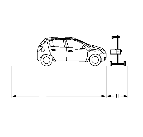
The surface on which the measuring instrument and the vehicle stand must be flat. The level of the ground must not vary by more than ± 0.5 mm / m.
| • | I = ± 0.1 mm / m |
| • | II = ± 0.5 mm / m |
Vehicle tyres must have specified air pressure. Defective headlamp lenses and mirrors as well as blackened bulbs must be replaced before adjusting.
The adjustment is performed at vehicle curb weight plus one person or 75 kg (165 lb) on the driver's seat. (Curb weight = weight of vehicle ready for use with completely filled fuel tank plus the weight of all equipment carried during use, e.g. spare wheel, tools, jack, first aid kit, emergency warning triangle, etc.).
Vehicles with manual level control must be adjusted to the specified basic pressure (0.8 bar at curb weight).
If manual headlamp range control is fitted, switch the ignition on and position the adjuster wheel of the light switch centre to "0".
The intersection between the horizontal and the ascending parts of the light/dark boundary (break point) must lie on the perpendicular through the central marking.
For easier determination of the intersection point, headlamp halves can be alternately covered and uncovered.
The headlamp adjusting equipment used must comply with the existing guidelines and the manufacturer's operating instructions must be observed.
The headlamp adjuster must be regularly checked by manufacturer's maintenance service.
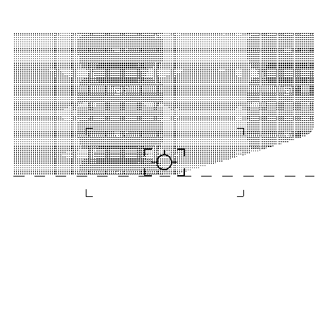
The headlamp adjuster is set up according to manufacturer's guidelines and is adjusted to 1.0 % inclination for the low beam or 2 % inclination for the fog lamp.
According to the directive 76/756, EEC the15° line is no longer required for the dipped beam on the measurement screen (illustration D 6213 shows adjustment for right hand drive vehicles). The adjustment direction can also be undertaken with headlamp adjustment equipment which shows the 15° line on the measurement screen.
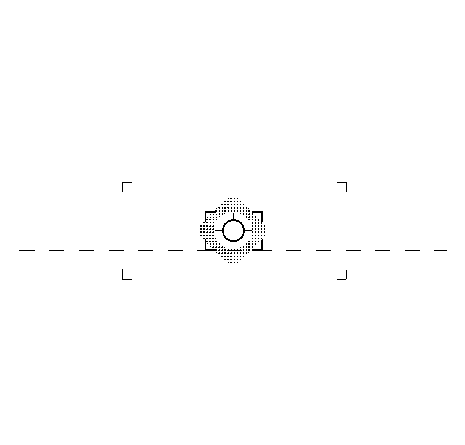
In headlamps where the main and dipped beam can be adjusted, the centre of the main beam must lie within the boundary corners around the central mark (illustration 2019515).
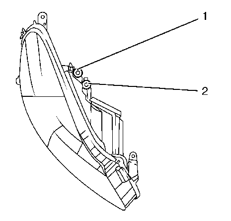
Headlamps: | |
1 | Bolt for vertical adjustment |
2 | Bolt for lateral adjustment |
Headlamps must be adjusted using a legally specified projection wall or with optical headlamp adjuster.
Vertical adjustment the light/dark boundary line left of the adjustment cross must run horizontally along the adjustment line.
Lateral adjustment the light-dark border must run horizontally from the left side up to the adjusting cross and from there on at an angle of up to approximately 15° towards the upper right. The beam inclination is 1.0 % on 10 m (33 ft).
Note: Carry out vertical adjustment first, then lateral adjustment. Check vertical adjustment again after lateral adjustment.
Headlamp Aiming Base
Visual Aiming Preparation Procedure
Note: Some state and local laws specify requirements for headlamp aim. Comply with all of these laws when performing any headlamp aiming operations.
Headlamp aim should be checked:
| • | When a new headlamp capsule is installed. |
| • | If service or repairs to the front end area have, or may have, disturbed the headlamps or their mounting. |
The aiming screen should meet the following criteria:
| • | The area will consist of a level surface large enough to allow for a vehicle and an additional 7.62 m (25 ft) measured from face of lamps to the front of the aiming screen. |
| • | The screen will be 1.52 m (5 ft) high x 3.66 m (12 ft) wide with a matte white surface well shaded from extraneous light, and properly adjusted to the floor on which the vehicle stands. Provisions should be made to align the aiming screen parallel with the vehicle. |
| • | The screen shall be provided with a fixed vertical centerline, two laterally adjustable vertical tapes, and one vertically adjustable horizontal tape. |
| • | If a regular commercial aiming screen is not available, the screen may consist of a vertical wall having a clear uninterrupted area approximately 1.83 m (6 ft) high and 3.66 m (12 ft) wide. The surface should be finished with a washable non-gloss white paint. |
| • | After the aiming screen has been set up in a permanent location, paint a reference line on the floor directly under the lens of the lamps to indicate the proper location of the headlamps when they are being aimed: |
| - | Distance between headlamps (1) |
| - | Center line of screen (2) |
| - | Adjustable vertical pointer (3) |
| - | Adjustable horizontal tape (4) |
| - | Diagram of light screen (5) |
| - | Vertical center line ahead of right headlamp pointer position (6) |
| - | 7.62 m (25 ft) (7) |
| - | Car axis (8) |
| - | Adjustable vertical pointer |
| - | Horizontal center line of lamps |
| - | Vertical center line ahead of left headlamp |
Prior to aiming the headlamps, the following steps must be taken:
- Remove any snow, ice or mud from the vehicle.
- The vehicle must have a full tank of gas.
- Stop all other work on the vehicle.
- If any service has been performed on the vehicle, make sure that all of the components are back in their original place.
- The vehicle must be on a level surface.
- The vehicle left tires must be aligned with the reference line extending from the screen with the headlamps aligned with the reference line.
- Do not load any cargo in the vehicle.
- The vehicle must contain approximately 75 kg (165 lb) on the driver seat.
- Inflate the tires to the proper pressure.
- Simulate the vehicle loads if the intended use of the vehicle is for hauling heavy loads or towing a trailer.
- Rock the vehicle in order to stabilize the suspension.
- Turn on the headlamps to low beam and observe the left and the top edges of the high intensity zone on the screen. The edges of the high intensity zone should fall within the specifications.
Headlamp Aiming Procedure
- Open the hood.
- Measure from the floor to the center of the headlamp bulb. Some headlamps have an aim dot marked on the headlamp lens.
- At the screen, measure from the floor and place the horizontal tape at the measured distance.
- Measure from the reference line on the floor to the left headlamp bulb centerline.
- At the screen, measure from the reference line and place the vertical tape at the measured distance.
- Measure from the reference line on the floor to the right headlamp bulb centerline.
- At the screen, measure from the reference line and place the vertical tape at the measured distance.
- Turn ON the low beam headlamps. Block the light from projecting onto the screen from the passenger side headlamp.
- Adjust the vertical aim screw of the headlamps to the specifications required by the state and the local authorities, or as shown in step number 8.
- Repeat the aiming procedure for the passenger side headlamp while blocking the light from projecting onto the screen from the driver side headlamp.
- Turn the headlamps OFF.
- Close the hood.
Note: DO NOT cover the headlamp. This may cause excessive heat build up.
Note: The headlamps can not be adjusted horizontally.
