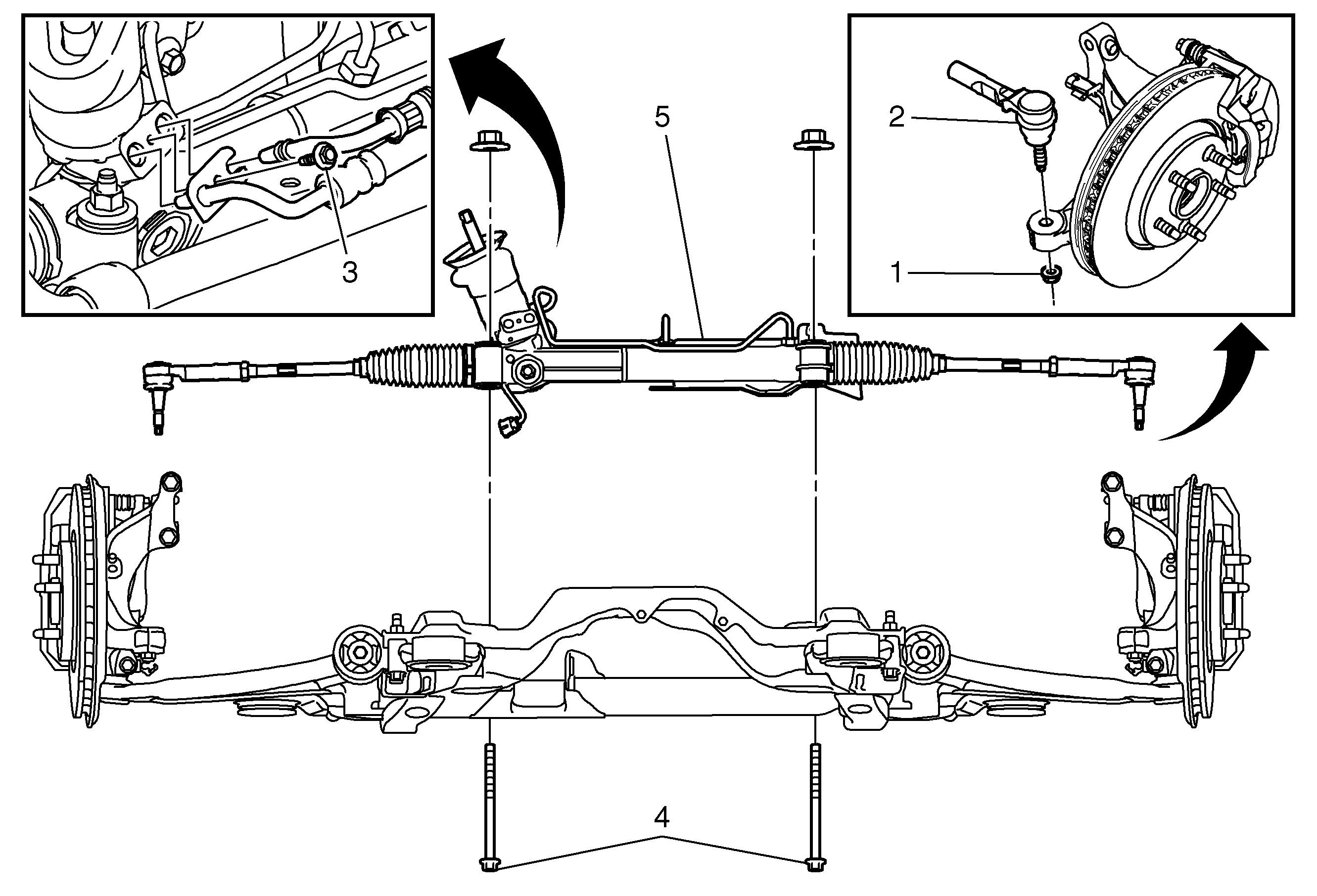
Callout
| Component Name
|
|
Caution: The steering column must be in the LOCK position before disconnecting the following components:
| • | The steering shaft coupling |
| • | The lower steering shaft |
Preliminary Procedures
- Remove the intermediate steering shaft lower bolt from the steering gear. Refer to
Intermediate Steering Shaft Replacement.
- Raise and support the vehicle. Refer to
Lifting and Jacking the Vehicle.
- Remove the front tire and wheel assemblies. Refer to
Tire and Wheel Removal and Installation.
- AWD-- Remove the propshaft. Refer to
Propeller Shaft Replacement.
- Using a suitable jack stand, support the frame assembly.
- Release the bolt to the rear transmission mount. Refer to
Transmission Rear Mount Replacement or
Transmission Rear Mount Replacement.
- Remove the rear fasteners to the frame the frame to body bolts. Refer to
Frame Replacement.
- Lower the rear part of the frame, maximum 50 mm in order to gain clearance to the steering gear.
|
1
| Steering Linkage Outer Tie Rod Nut (Qty: 2)
Caution: Refer to Fastener Caution in the Preface section.
Tighten
35 N·m(26 lb ft) |
2
| Steering Linkage Outer Tie Rod (Qty: 2)
ProcedureRemove the steering linkage outer tie rod. Refer to
Steering Linkage Outer Tie Rod Replacement.
|
3
| Steering Gear Inlet and Outlet Hose Fastener
Procedure
- Place drain pans under the vehicle to catch any power steering fluid.
- Install NEW steering gear oil seals.
Tighten
9 N·m (80 lb in) |
4
| Steering Gear Bolt (Qty: 2)
ProcedureInstall new bolts.
Tighten
110 N·m (81 lb ft) + 150 degrees |
5
| Steering Gear
Procedure
- If equipped with variable effort steering, disconnect electrical connector.
- Fill and bleed the power steering system. Refer to
Power Steering System Bleeding.
- Adjust the front toe. Refer to
Front Toe Adjustment.
|

