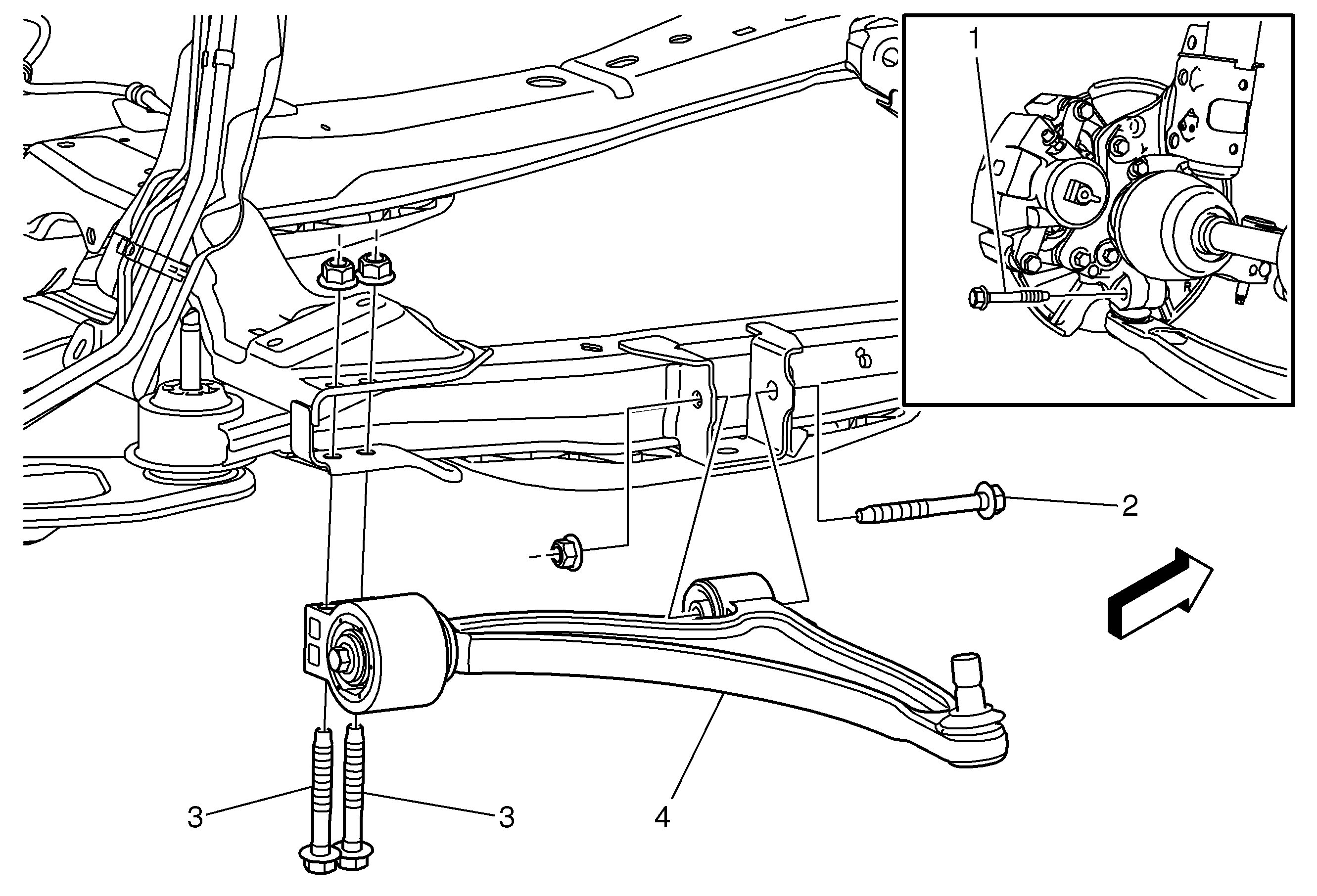
Callout
| Component Name
|
|
Caution: The ball stud must not rotate during disassembly or reassembly. Hand tools must be used to keep the ball stud from rotating. If air tools are used and the stud is allowed to rotate, damage to
the ball stud and/or stud mounting hole may occur.
Preliminary Procedure
- Raise and support the vehicle. Refer to
Lifting and Jacking the Vehicle.
- Remove the tire and wheel assembly. Refer to
Tire and Wheel Removal and Installation.
|
1
| Lower Ball Joint Fastener
Caution: Refer to Fastener Caution in the Preface section.
Procedure
- Discard the bolt and install a NEW lower ball joint bolt. DO NOT re-use the lower ball joint bolt.
- Start the nut by hand before tightening.
- Tighten the bolt and then reverse the nut 3/4 of a turn.
Tighten
30 N·m(22 lb ft) + 60 degrees |
2
| Front Lower Control Arm Fastener
Procedure
- Load the front suspension with the proper jack stand before tightening the bolts to specifications.
- Enter the nut by hand before tightening.
- Install NEW bolt
Tighten
90 N·m(66 lb ft) + 100 degrees |
3
| Front Lower Control Arm Fastener (Qty: 2)
Procedure
- Load the front suspension with the proper jack stand before tightening the bolts to specifications.
- Enter the nut by hand before tightening.
- Install NEW bolt
Tighten
70 N·m(52 lb ft) + 80 degrees |
4
| Front Lower Control Arm Bushing Fastener
Procedure
- Load the front suspension with the proper jack stand before tightening the bolts to specifications
- Install NEW bolt.
- Start the nut by hand before tightening.
- Tighten the screw using the
GE-6600-2 torque wrench
.
Tighten
40 N·m (30 lb ft) + 30 degrees
Special ToolsGE-6600-2 Torque Wrench
For equivalent regional tools. Refer to
Special Tools.
|
5
| Lower Control Arm Assembly
Procedure
- Rotate the forward edge of the steering knuckle outboard to provide access for the TBD separator
- Loosen but DO NOT remove the nut until the ball stud has been separated from the knuckle.
- Separate the ball stud from the knuckle, using the TBD separator.
- Verify wheel alignment. Refer to
Wheel Alignment Specifications.
Special ToolsTBD Ball Joint Separator
For equivalent regional tools. Refer to
Special Tools.
|

