For 1990-2009 cars only
Stabilizer Shaft Replacement GNE

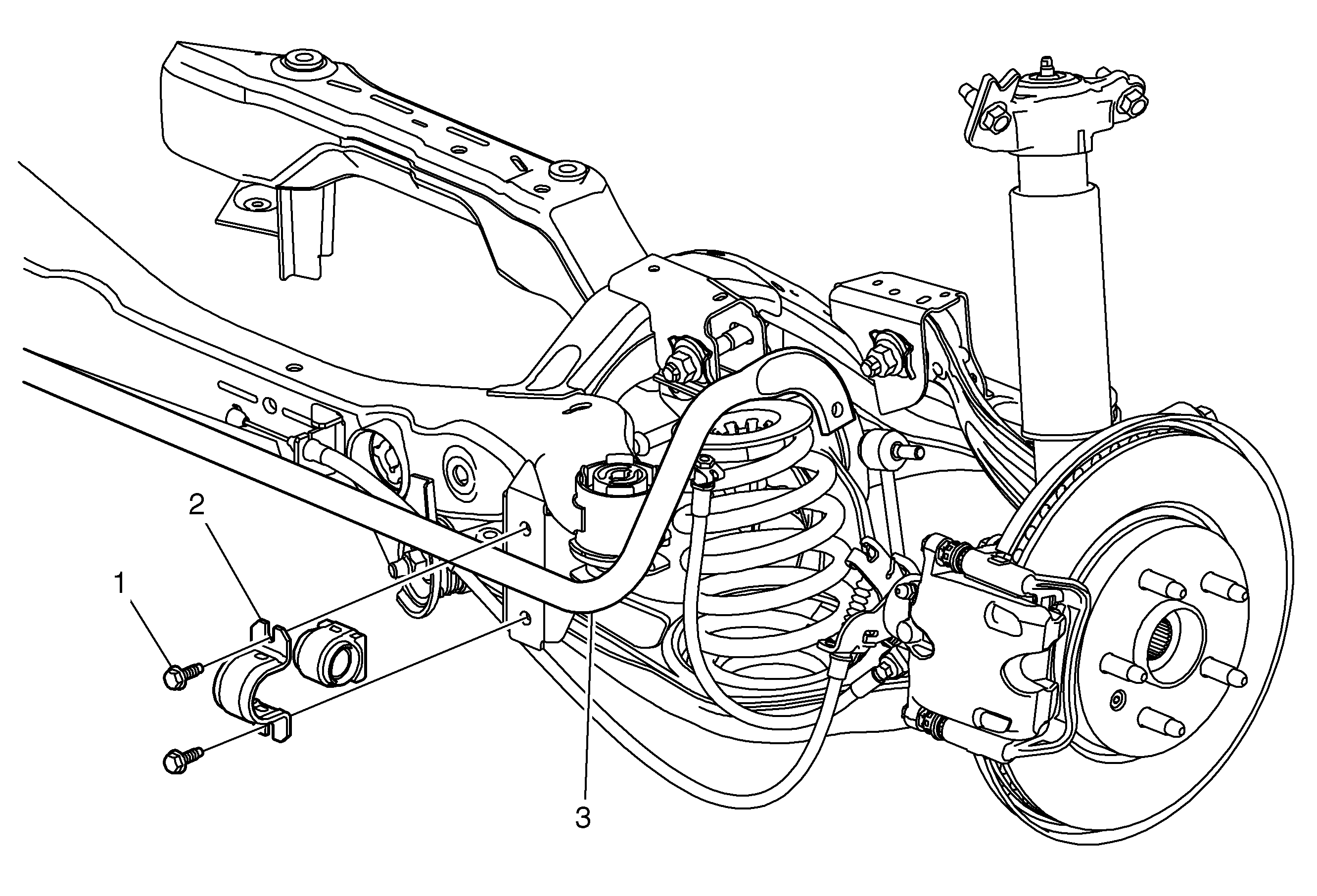
Callout | Component Name |
|---|---|
Preliminary Procedure
| |
1 | Stabilizer Shaft Insulator Fastener (Qty: 4) Caution: Refer to Fastener Caution in the Preface section. Tighten |
2 | Stabilizer Shaft Bracket |
3 | Stabilizer Shaft ProcedureReplace insulator if necessary. |
Stabilizer Shaft Replacement GNC
Removal Procedure
- Raise and support the vehicle. Refer to Lifting and Jacking the Vehicle.
- Remove the tire and wheel assembly. Refer to Tire and Wheel Removal and Installation.
- Remove the rear muffler assembly. Refer to Exhaust Muffler Replacement.
- Remove the fasteners from the trailing arm to body. Refer to Trailing Arm Replacement.
- Remove the rear spring. Refer to Rear Spring Replacement.
- Remove the park brake cables from the trailing arms. Refer to Parking Brake Rear Cable Replacement.
- Without disconnecting the hydraulic brake hose from the caliper, remove and support the brake calliper. Refer to LINK.
- Remove the lower shock absorber bolts. Refer to Shock Absorber Replacement.
- Support and secure adjustable jack stands to the rear support.
- Mark up support position to body with spray paint.
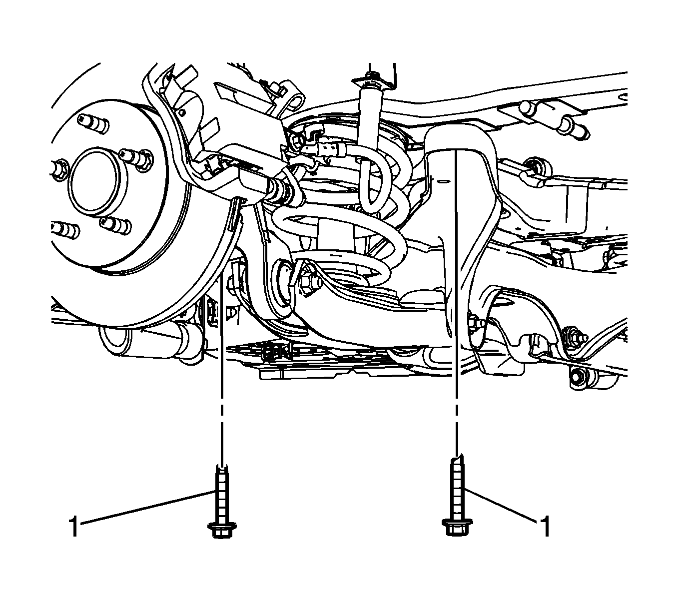
- Remove the mounting bolts for the support. Refer to Support Replacement.
- Lower the support enough to gain access to the rear stabilizer shaft insulator clamps mounting bolts.
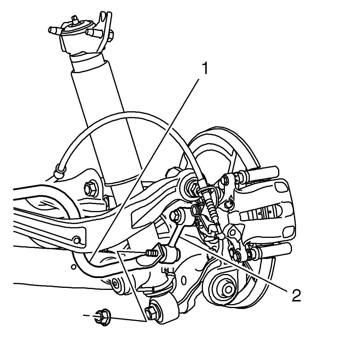
- Remove the stabilizer shaft (1) from the stabilizer shaft link (2).
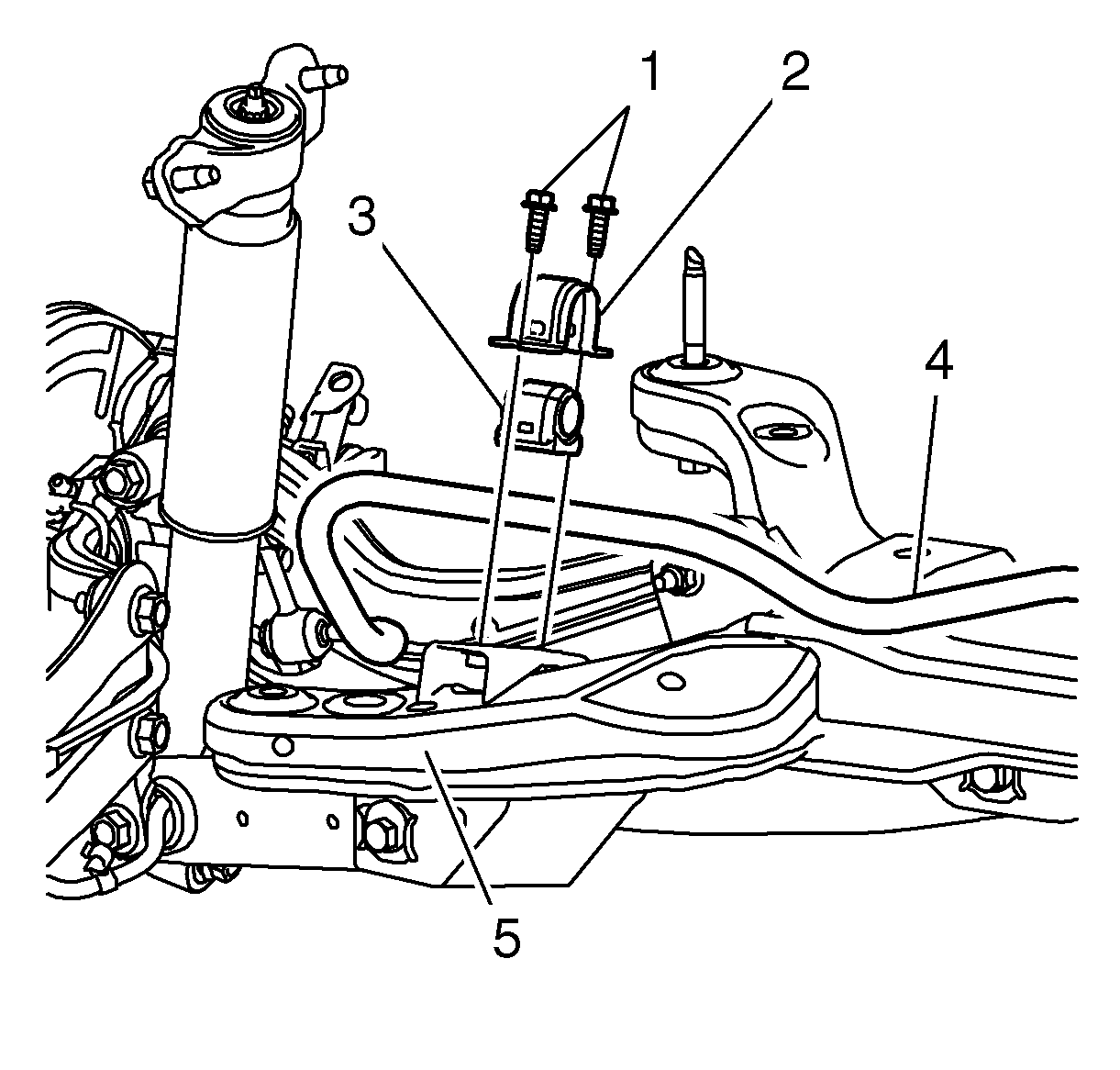
- Remove the stabilizer shaft bolts (1).
- Remove the stabilizer shaft assembly (4) from the support (5).


Installation Procedure
- Load the suspension with the proper jack stand before tightening the bolts to specifications.
- Install the stabilizer shaft (4) on the support (5).
- Install the clamp bolts (1) and tighten to 22 N·m (16 lb ft).
- Install the stabilizer shaft (1) to stabilizer shaft link (2) and tighten to 50 N·m (37 lb ft).
- Raise the rear support back into position.
- Install the rear support bolts (1). Refer to Support Replacement.
- Install the lower shock absorber mounting bolts. Refer to Shock Absorber Replacement.
- Install the rear brake calipers. Refer to Rear Brake Caliper Replacement.
- Install the fasteners from the trailing arm to body. Refer to Trailing Arm Replacement.
- Install the rear springs. Refer to Rear Spring Replacement.
- Remove the adjustable jack stands from the rear support.
- Install the park brake cables on the trailing arms. Refer to Parking Brake Rear Cable Replacement.
- Install the rear muffler assembly. Refer to Exhaust Muffler Replacement.
- Install the tire and wheel assemblies. Refer to Tire and Wheel Removal and Installation.
- Lower the vehicle.

Caution: Refer to Fastener Caution in the Preface section.


