General
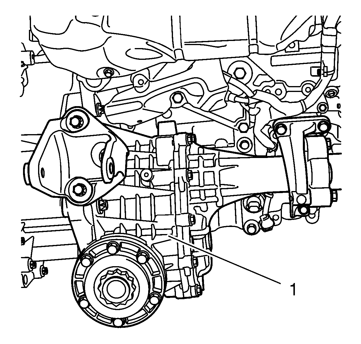
The transfer case (1) is located to the right of the transmission, to which it is bolted.
Its primary function is to take power from the transmission and transfer it via a hypoid gear to the differential clutch via the propeller shaft. The intermediate shaft runs to the right-hand front wheel through the transfer case.
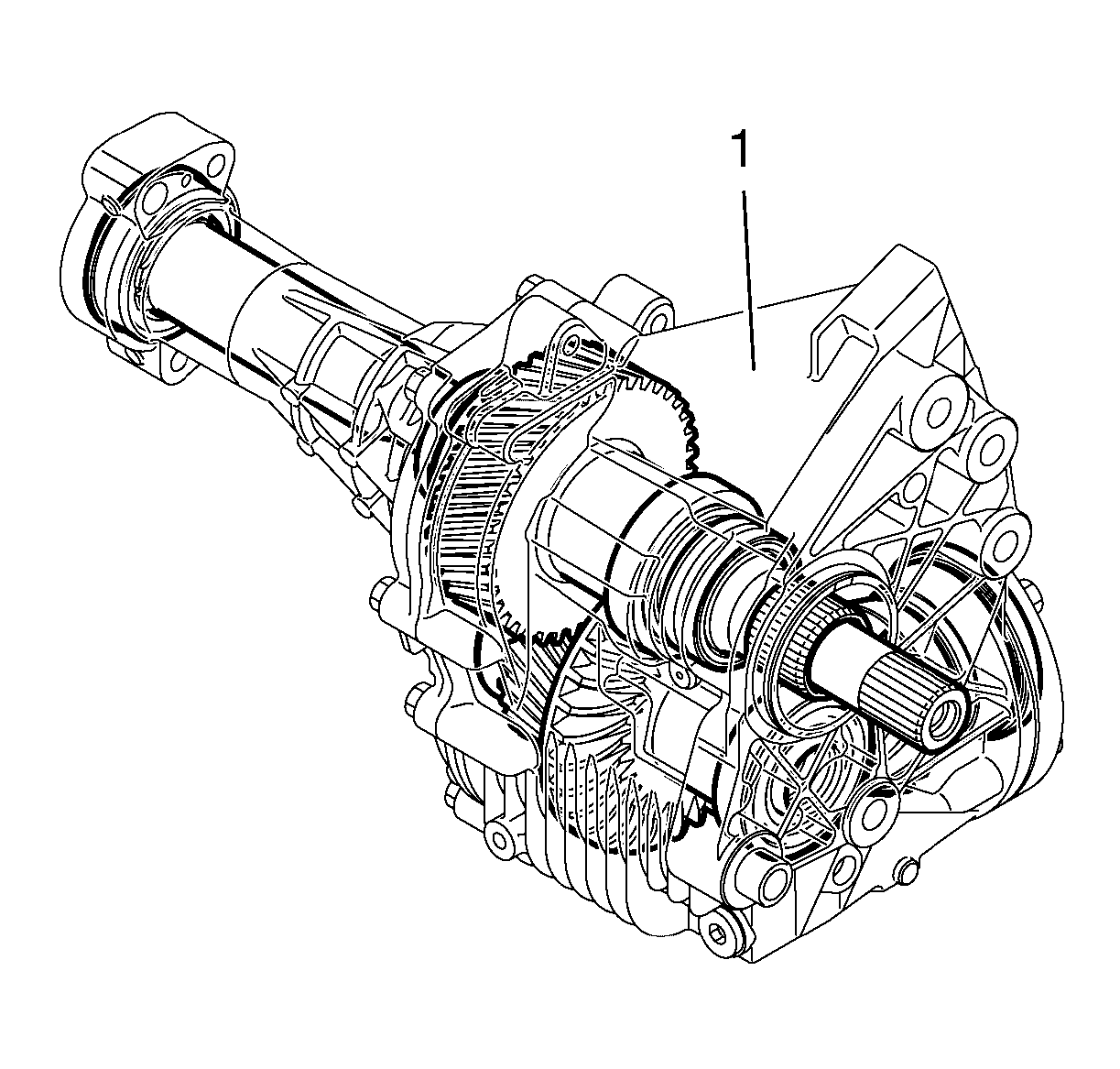
The transfer case (1) is fully mechanical.
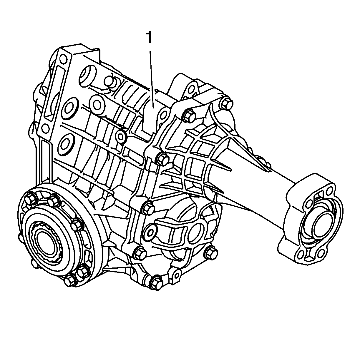
During manufacture the transfer case (1) is filled with oil, which then does not require changing. The correct type of oil must be used without exception when filling. The incorrect type of oil may discard the transfer case. Refer to Adhesives, Fluids, Lubricants, and Sealers.
Housing and Cover
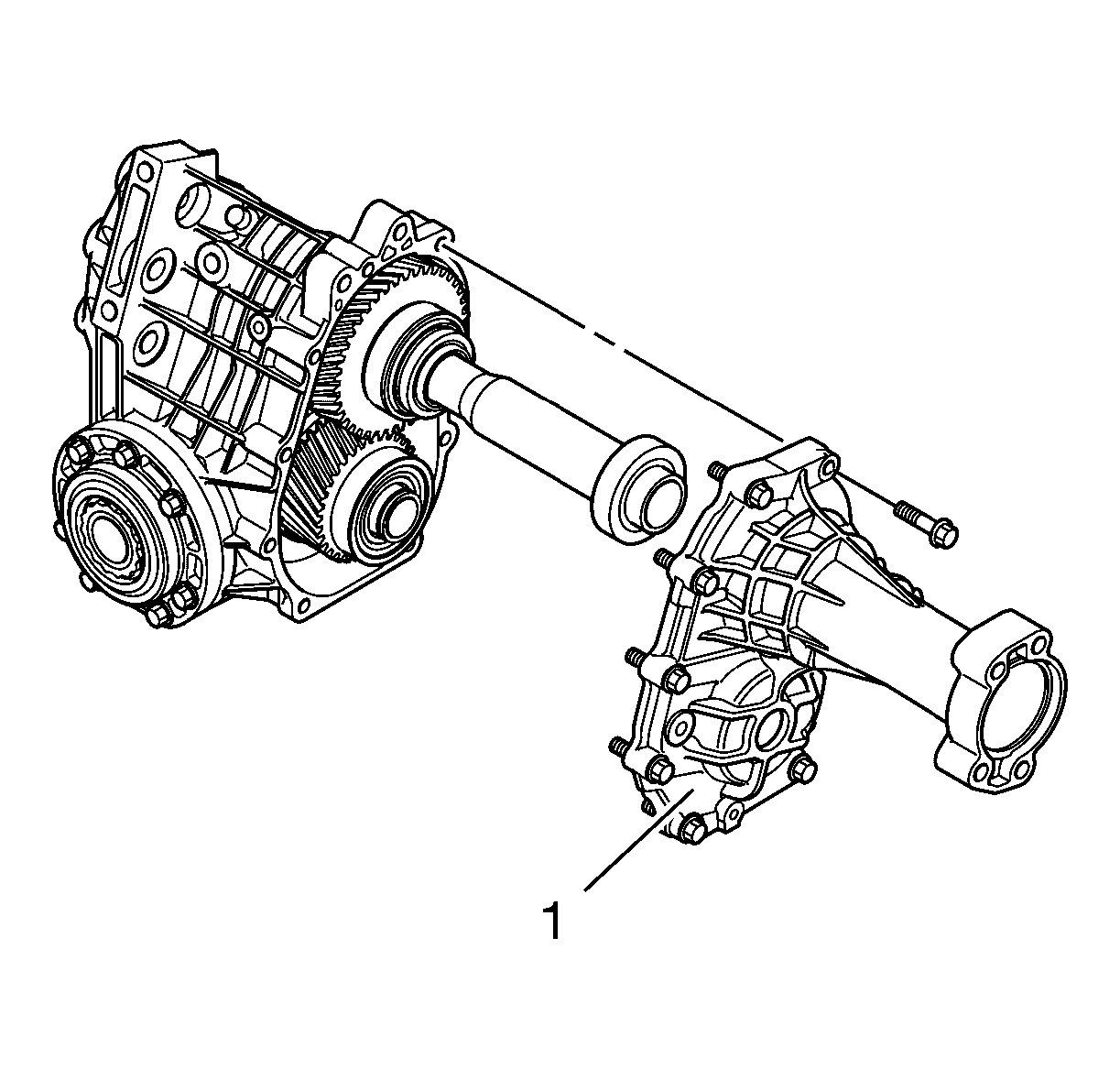
The transfer case housing and transfer case rear extension are produced from a high-pressure cast aluminium alloy. A number of reinforcement ribs are fitted in suitable locations to strengthen the transfer case housing and cover (1), and these constitute a vital part of the cooling for the transfer case. The transfer case rear extension is bolted to the housing with 9 bolts, 2 rear extension locating pins govern their relative position. The mating face between transfer case housing and transfer case rear extension is sealed using sealant.
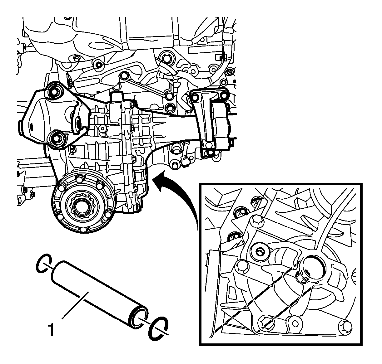
The transfer case housing is bolted to the transmission with 4 transfer case bolts, of which one bolt is accessible via the idler gear shaft that runs inside the crown wheel shaft. A location bushing (1) on the transfer case housing runs into the transmission to ensure that the relative position is correct. The connection between the transfer case housing and the transmission is sealed with an O-ring. Two opposite radial seals, seal the input shaft, and there is an overflow hole in the transfer case housing between the radial seals.
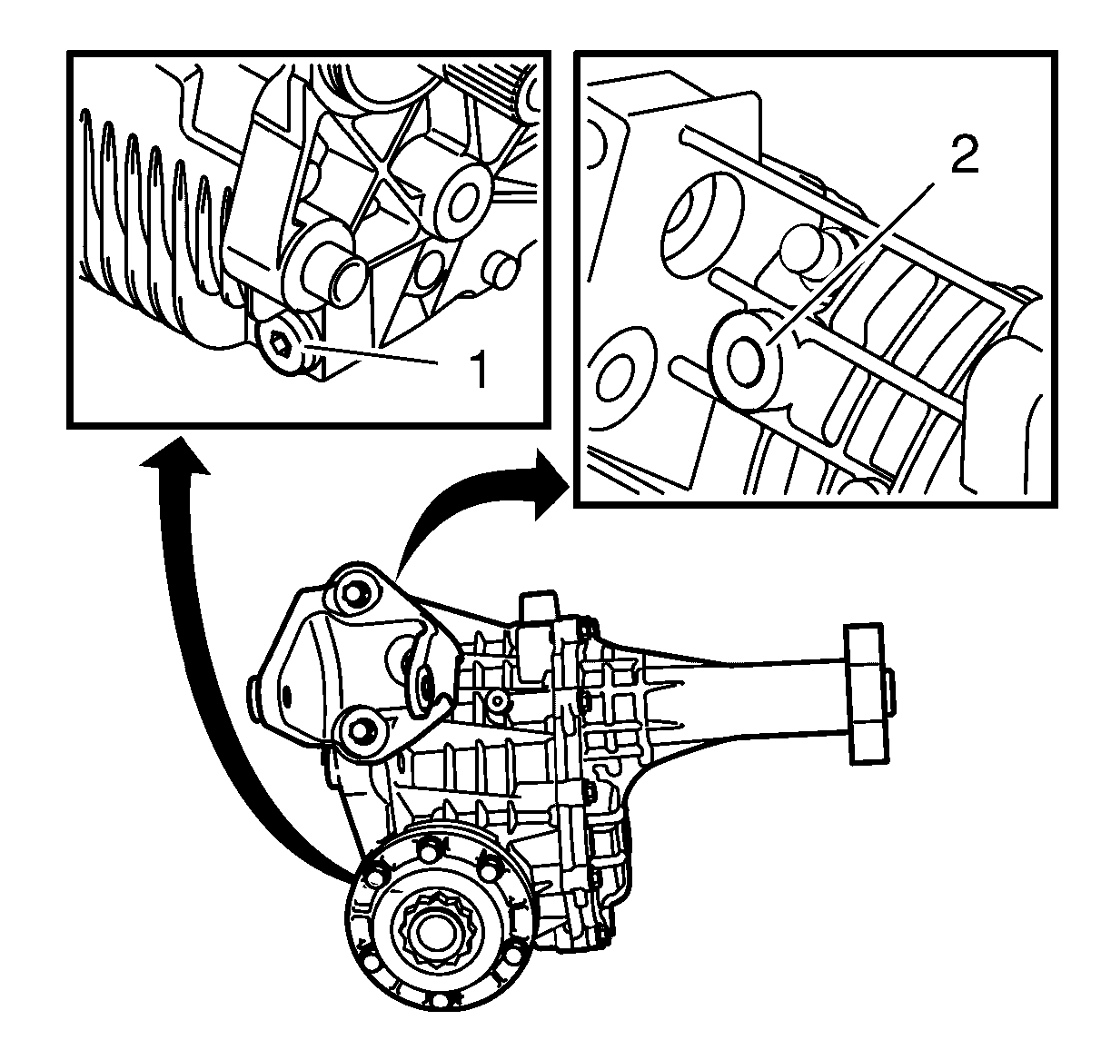
A transfer case vent (1) is located above the transfer case housing. There is a magnetic oil drain plug (2) fitted in the bottom. The transfer case housing also constitutes the attachment point for the rear unit's mounting. A bracket for this is bolted to the housing with 3 bolts. Inside the transfer case housing are bearing races for the input shaft and the crown wheel shaft, behind the bearing races are shims to provide the correct bearing preload.
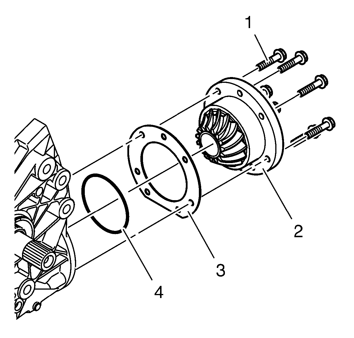
The rear output shaft flange (2) is bolted to the transfer case housing with 7 bolts (1) and sealed to the transfer case housing with an O-ring (4). A shim (3) guides the rear output shaft flange gear insert into the crown wheel. There are bearing races in the transfer case housing for the input shaft and the crown wheel shaft, there is a shim behind the bearing races to provide the correct bearing preload.
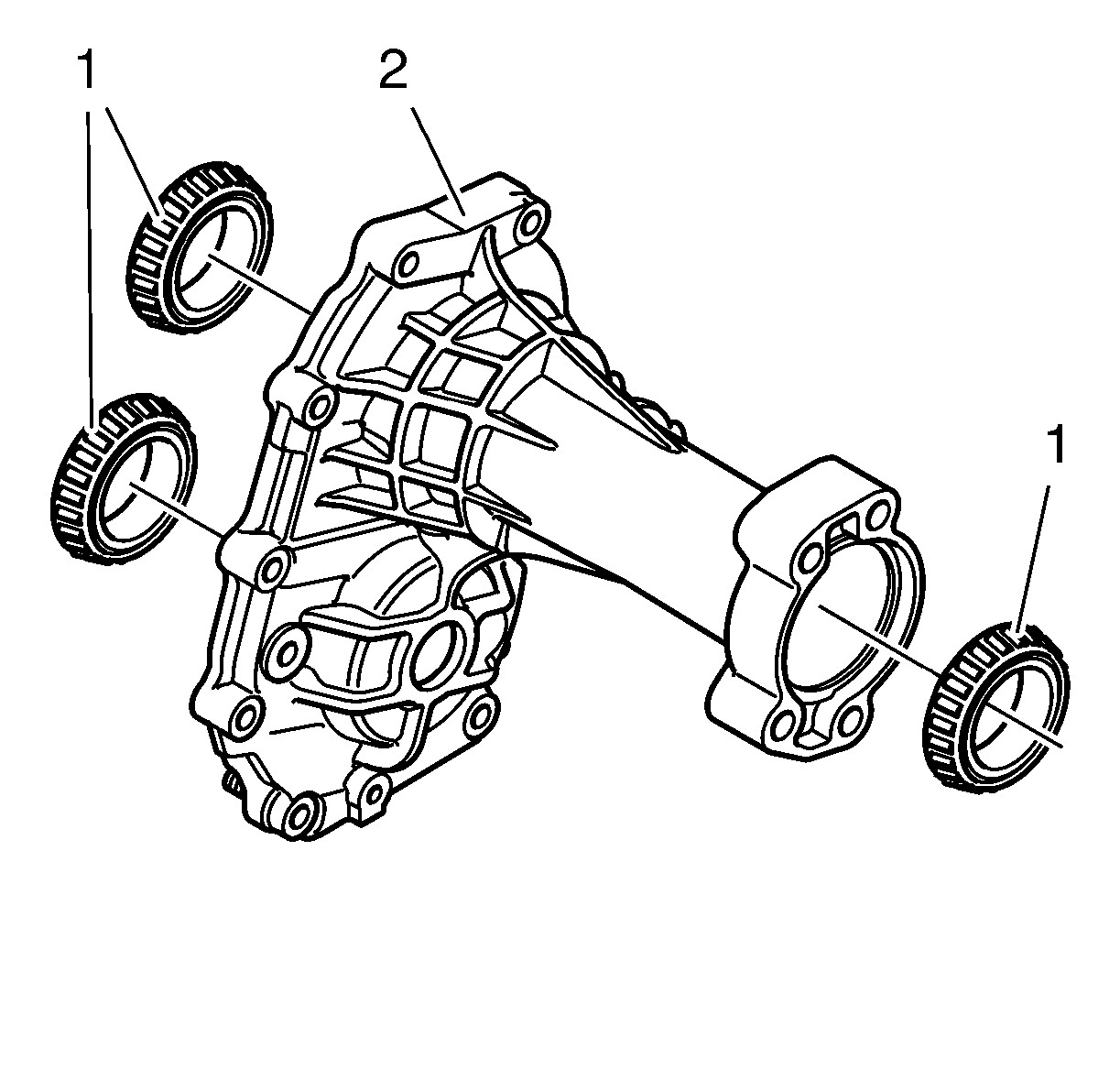
There are bearing races (1) in the transfer case rear extension (2) for the input shaft, crown wheel shaft as well as a support bearing for the intermediate shaft for the right-hand front wheel. The oil fill plug is fitted in the cover.
The transfer case rear extension has a neck through which the intermediate shaft for the right-hand front wheel runs. The neck serves partly as a holder for the intermediate shafts support bearing, and partly as an attachment point for the transfer case to the engine. The intermediate shaft support bearing is a single-row sealed permanently-lubricated groove ball bearing and is locked with a transfer case intermediate shaft retaining ring in the transfer case rear extension housing.
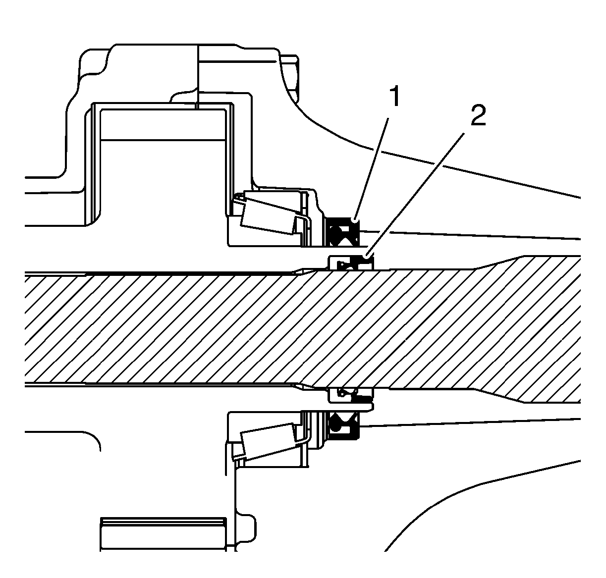
A radial seal (1) is fitted in the transfer case rear extension at the input shaft so that the oil from the transfer case does not seep out at the neck of the transfer case rear extension. Inside the input shaft is a radial seal (2) that seals against the intermediate shaft to avoid oil from the transmission seeping out at the neck of the transfer case rear extension.
Input Shaft
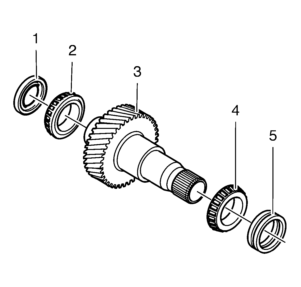
The function of the input shaft (3) is to transfer power from the transfer case. In one end the shaft is equipped with splines which are inserted into the transmission differential housing. Consequently the speed of the input shaft is the same as the transmission crown wheel. Fitted in the transfer case housing are 2 opposite radial seals (5) to seal the input shaft. The other end of the input shaft is equipped with an internal radial seal to seal against the right-hand front wheel's intermediate shaft which runs inside the input shaft. Externally the shaft is sealed with a radial seal (1).
There is a gear on the shaft with helical teeth in order to reduce noise and to increase the engagement area of the teeth. The gear is engaged with a gear wheel on the crown wheel shaft.
The shaft is mounted in 2 conical roller bearings (2, 4). The bearings are given the correct preload at manufacture by means of shims being fitted behind the bearing races in the housing and cover respectively.
Crown Wheel Shaft
The crown wheel shaft is located under the input shaft and is driven by the gear on the input shaft. The shaft has a relatively large diameter and is hollow.
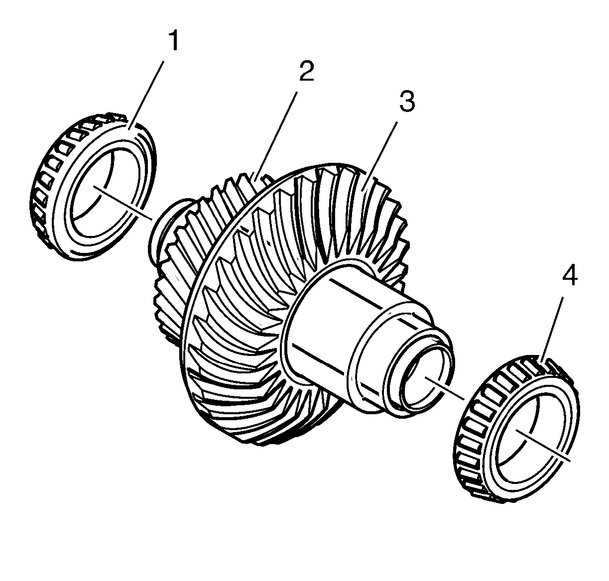
The crown wheel shaft consists of a helical gear wheel (2) and a crown wheel (3). The helical gear wheel is driven by the input shaft. In turn the crown wheel drives the rear output shaft flange. The crown wheel and rear output shaft flange are matched to each other.
The shaft is mounted in 2 conical roller bearings (1, 4). The bearings are given the correct preload at manufacture by means of shims being fitted behind the bearing races in housing and cover respectively.
Rear Output Shaft Flange
The rear output shaft flange with associated bearing and radial seal constitute one unit which is bolted to the transfer case housing with 7 bolts. A shim provides the rear output shaft flange with the correct gear contact to the crown wheel. The rear output shaft flange is matched together with the crown wheel.
The rear output shaft flange, which together with the rear output shaft flange gear constitutes one unit, is mounted with 2 conical roller bearings, fitted towards each other. The bearing closest to the rear output shaft flange gear absorbs forces that attempt to press the rear output shaft flange gear from the crown wheel, while the farther bearing absorbs the forces that attempt to press the rear output shaft flange gear into the crown wheel.
The rear output shaft flange is hollow and is equipped with internal splines in which the pin on the propeller shaft's front drive shaft universal joint is fitted.
The pin is equipped with a spring-loaded ring which locks it into a groove in the rear output shaft flange.
