GM Service Manual Online
For 1990-2009 cars only

Adjust Link Replacement GNC
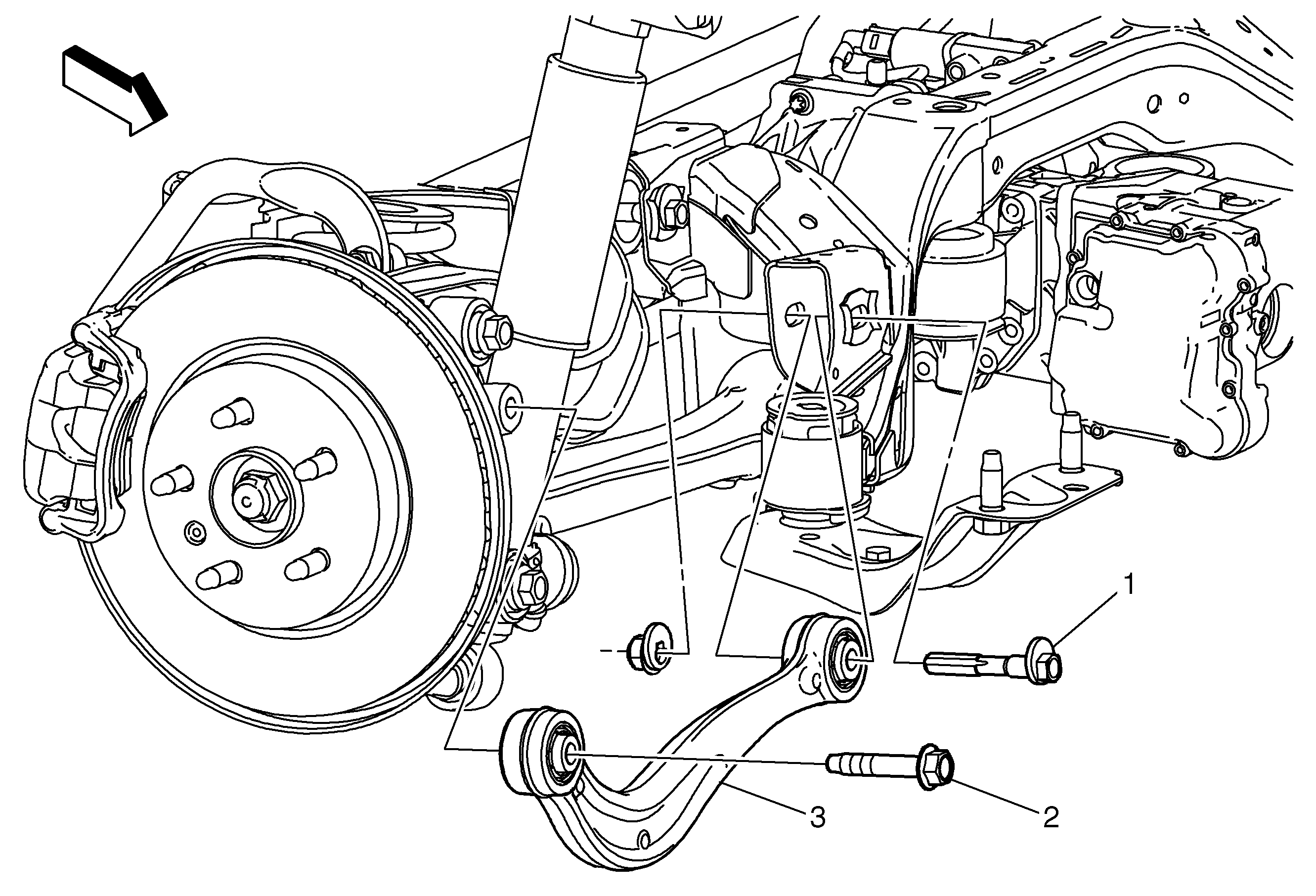

Object Number: 2018685  Size: MF

Callout

Component Name

Preliminary Procedures

  1. Raise and suitably support the vehicle. Refer to Lifting and Jacking the Vehicle.
  2. Remove the rear tire and wheel assembly. Refer to Tire and Wheel Removal and Installation.

1

Rear Suspension Link Inner Fastener

Caution: Refer to Fastener Caution in the Preface section.

Procedure

Apply torque on the nut.

Tighten
150 N·m (111 lb ft)

2

Rear Suspension Link Outer Fastener

Procedure

Install a NEW bolt.

Tighten
150 N·m (111 lb ft) + 60 degrees + 15 degrees

3

Adjust Link

Procedure

  1. Use a proper jack stand to load the knuckle when tightening the fasteners.
  2. After installation, check the rear alignment. Refer to Wheel Alignment Measurement.

Adjust Link Replacement GNE


Object Number: 2018685  Size: MF

Callout

Component Name

Preliminary Procedures

  1. Raise and suitably support the vehicle. Refer to Lifting and Jacking the Vehicle.
  2. Remove the rear tire and wheel assembly. Refer to Tire and Wheel Removal and Installation.

1

Rear Suspension Link Inner Fastener

Caution: Refer to Fastener Caution in the Preface section.

Procedure

  1. Remove nut and washer from adjust link inner fastener.
  2. Support the fuel tank using a proper jack stand.
  3. Remove fuel tank strap and loosen the other fuel tank strap fastener.
  4. Lower the fuel tank to get access to adjust link inner fastener.

Tighten
150 N·m (111 lb ft)

2

Rear Suspension Link Outer Fastener

Procedure

Install NEW bolt.

Tighten
150 N·m (111 lb ft) + 60 degrees + 15 degrees

3

Adjust Link

Procedure

  1. Use a proper jack stand to load the knuckle when tightening the fasteners.
  2. After installation, check the rear alignment. Refer to Wheel Alignment Measurement.