For 1990-2009 cars only
Removal and Inspection Procedure
Tools Required
| • | J 41681 Clutch Spring Compressor |
| • | J 8001 Dial Indicator Set |
| • | J 26900-13 Magnetic Base |
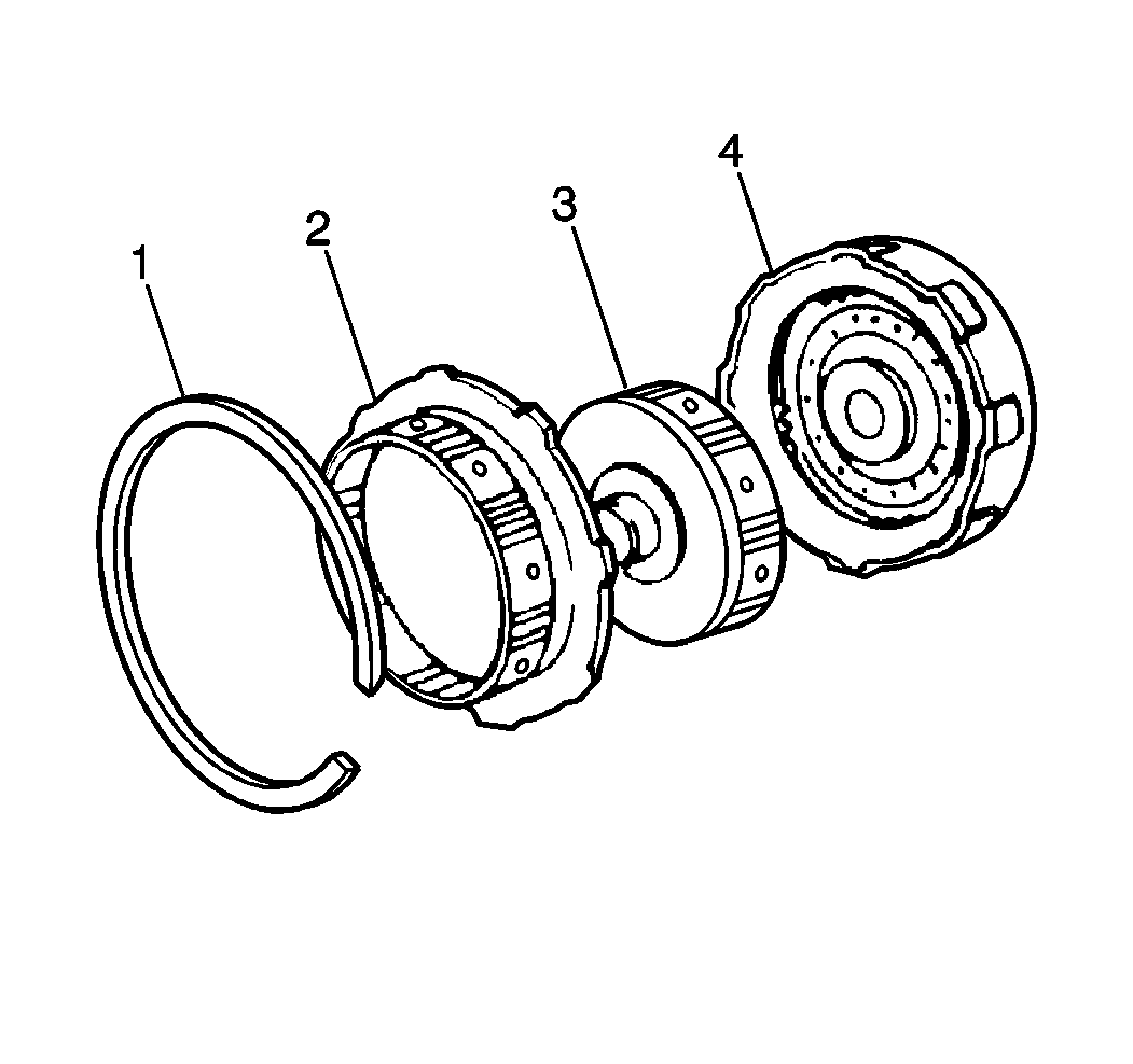
- Remove the following components from the input shaft:
- Remove the following components from the input shaft:
- Temporarily install the direct clutch input hub (1) and the snap ring (2) into the forward clutch.
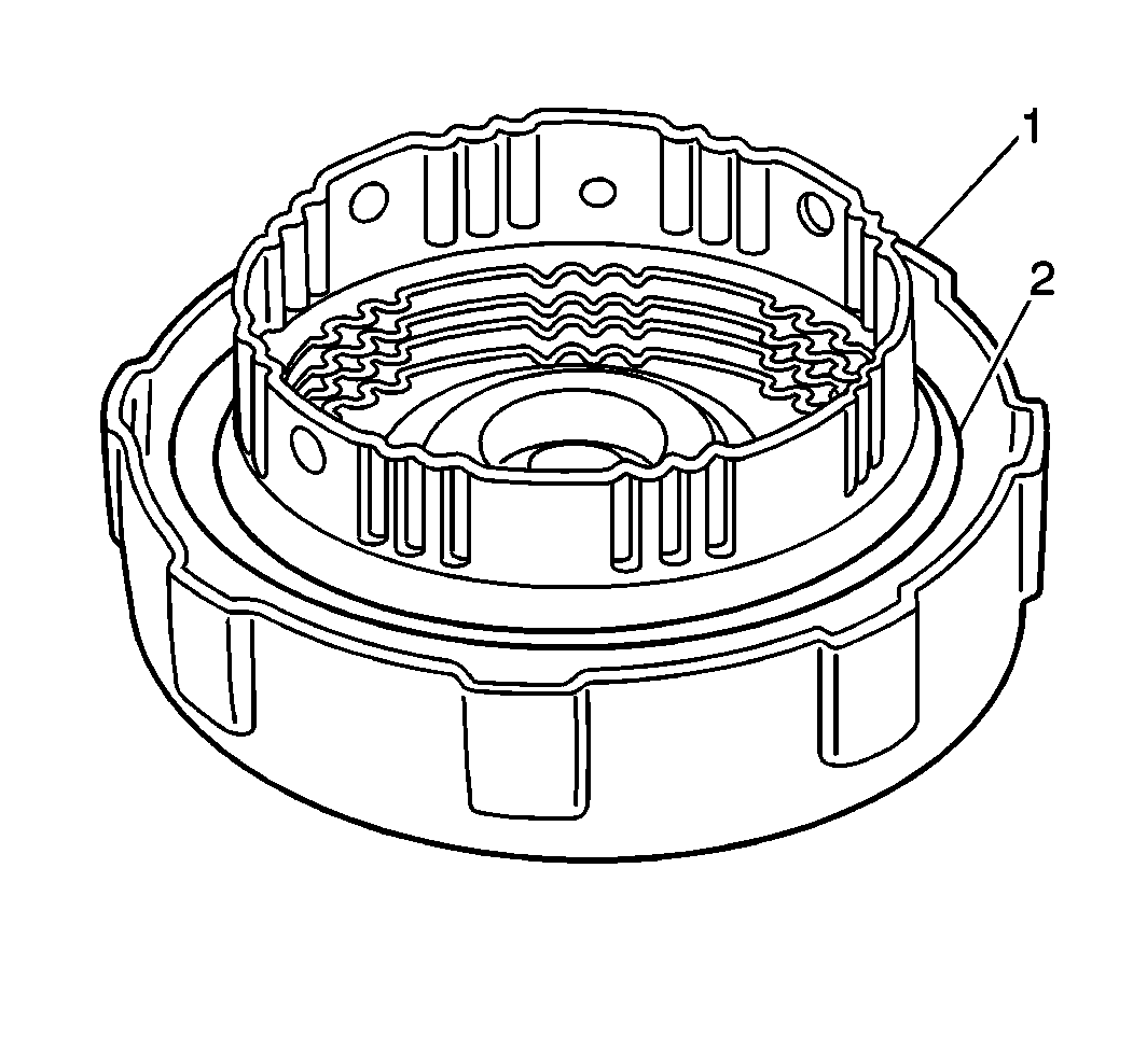
- Temporarily install the forward clutch (1) into the overdrive case (2).
- Measure the forward clutch piston stroke using the J 8001 and the J 26900-13 :
- Remove the forward clutch from the overdrive case.
- Remove the direct clutch input hub and snap ring from the forward clutch hub.
- Remove the following forward clutch hub components:
- Compress the forward clutch piston return springs using the J 41681 and a press while removing the snap ring.
- Remove the forward clutch piston return springs.
- Install the forward clutch to the overdrive case.
- Apply low compressed air pressure to the fluid passage at the RH of the overdrive case in order to remove the forward clutch piston.
- Remove the forward clutch piston O-rings.
- Measure the free length of the forward clutch piston return springs.
- Clean all forward clutch components.
- Allow the components to air dry.
- Inspect the forward clutch disc for excessive wear or damage. Replace as necessary.
- Inspect the forward clutch piston for cracks or porosity. Replace as needed.
- Shake the piston in order to inspect the forward clutch piston check ball free movement.
- Apply low compressed air pressure to the check ball opening in order to check for leaks. Repair or replace as necessary.
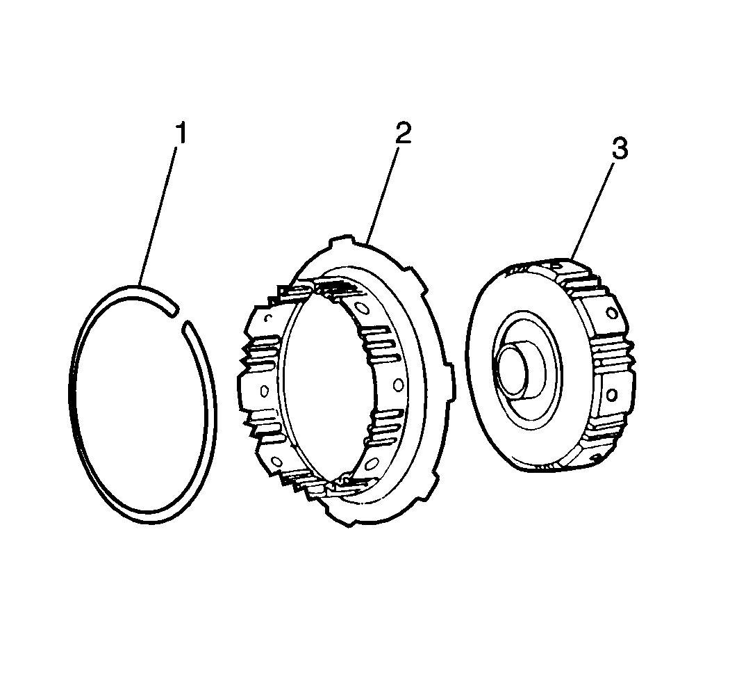
| • | The snap ring (1) |
| • | The direct clutch input hub (2) |
| • | The forward clutch hub (3) |
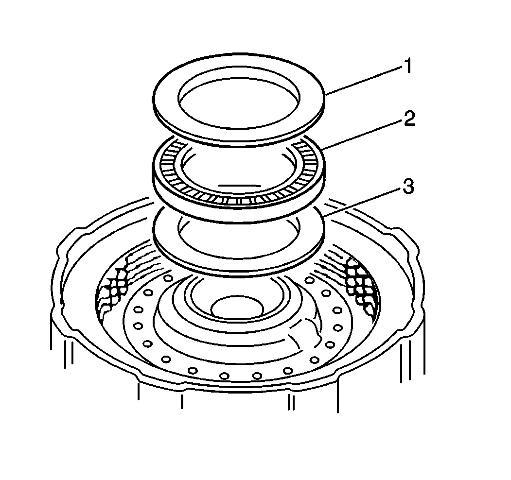
| • | The thrust bearing No. 2 race (1) |
| • | The thrust rear bearing race (3) |
| • | The forward clutch thrust bearing (2) |
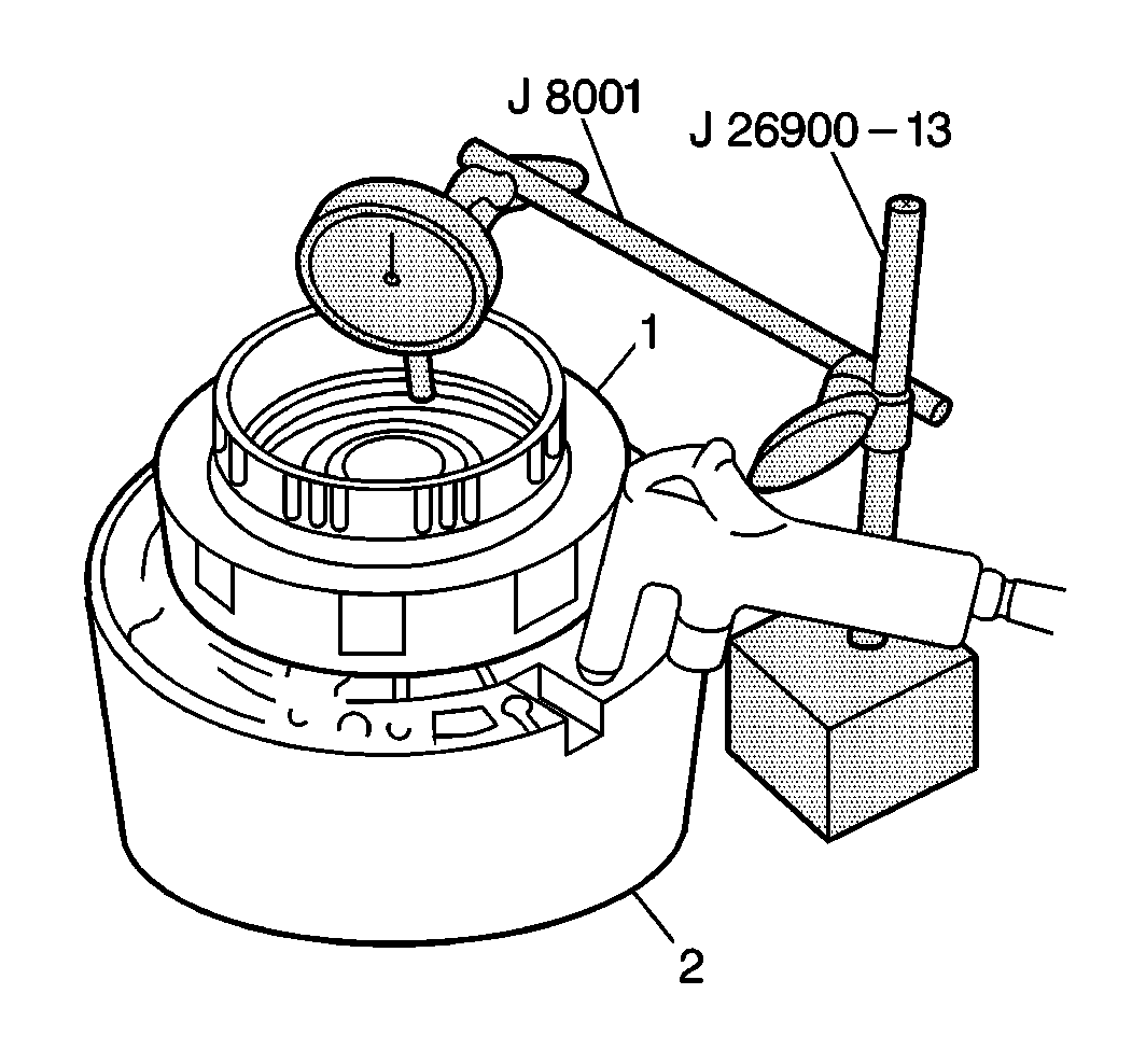
| 5.1. | Place the J 8001 plunger on the forward clutch piston. |
| 5.2. | Apply 392-785 kPa (57-114 psi) of compressed air into the fluid passage at the RH of the cut in the overdrive case. |
| 5.3. | Take the measurement. |
Specification
Forward clutch piston stroke (standard): 1.40-2.24 mm (0.056-0.088 in)
| 5.4. | If the forward clutch piston stroke is not within specifications, install a 1.80 mm (0.071 in) or 2.00 mm (0.079 in) clutch disc in order to adjust. |
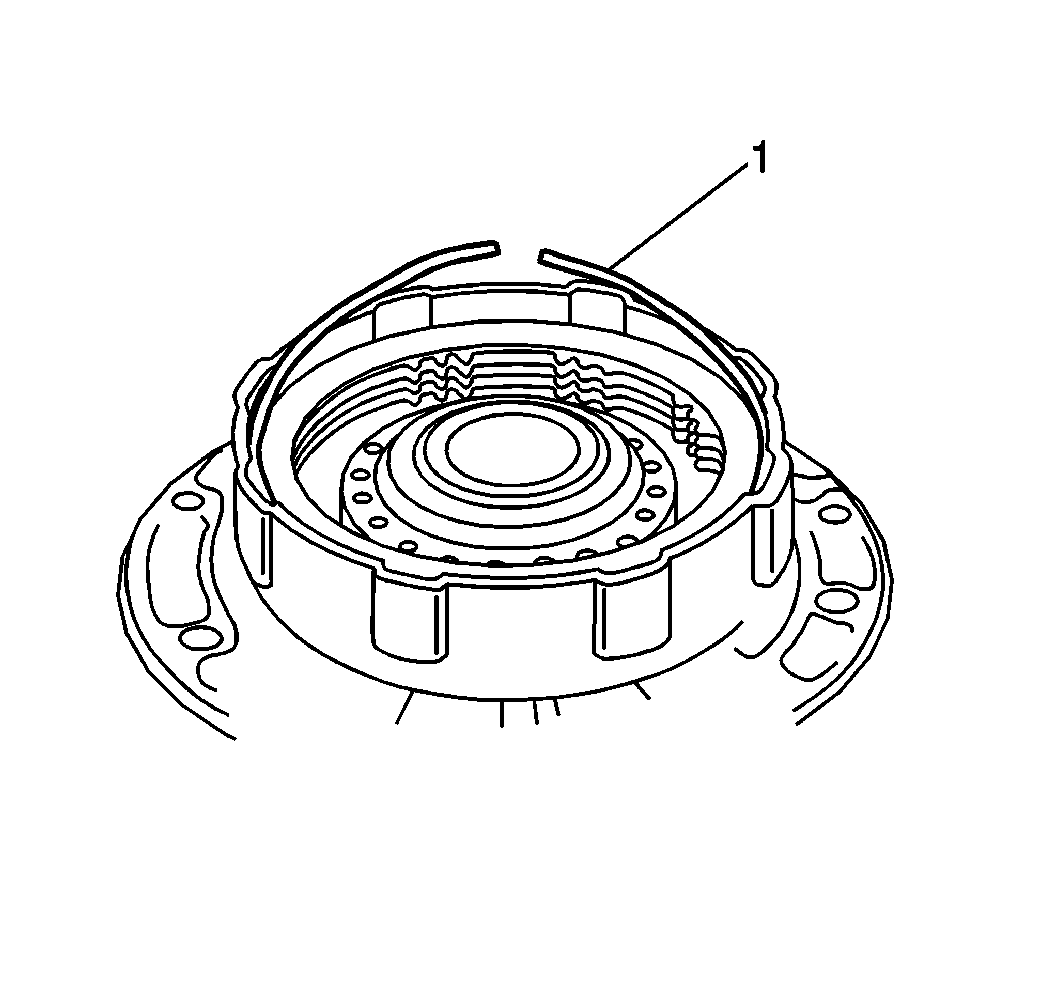
| • | The snap ring (1) |
| • | The clutch plates |
| • | The discs |
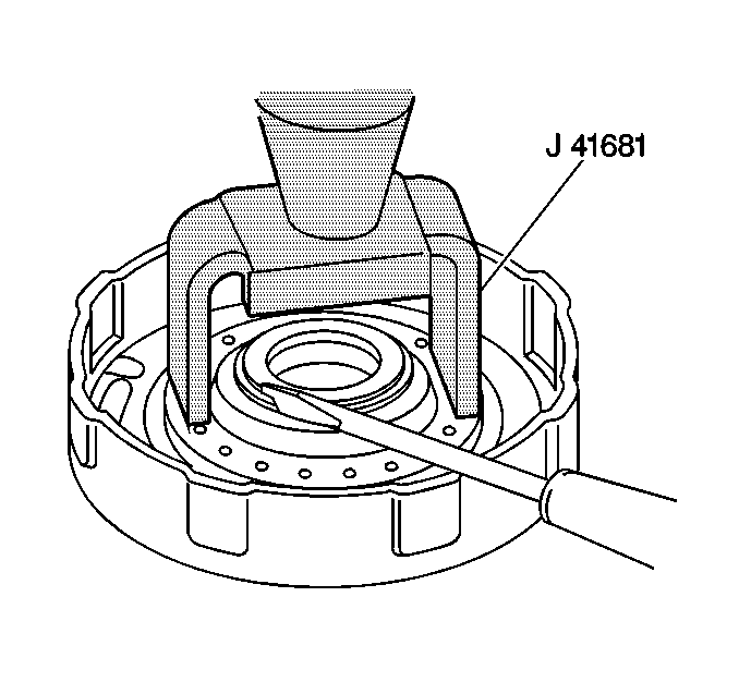
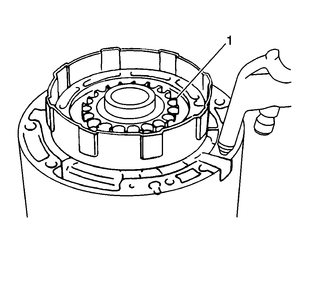
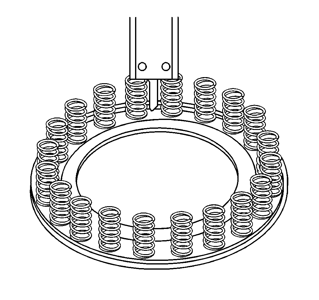
Specification
Forward clutch piston return spring free length (standard): 15.10 mm
(0.0594 in)
Replace if not within specifications.
Installation Procedure
Tools Required
| • | J 41681 Clutch Spring Compressor |
| • | J 36850 Transjel® Transmission Assembly Lubricant |
- Install a new O-ring to the forward clutch piston.
- Lubricate the O-ring with A/T fluid.
- Install the piston to the forward clutch drum.
- Install the piston return springs.
- Install the spring retaining plate.
- Compress the forward clutch piston return springs using the J 41681 while installing the snap ring (1).
- Install the forward clutch discs and plates in the following order:
- Install the forward clutch snap ring.
- Install the following components, lubricating with J 36850 :
- Install the forward clutch hub (3).
- Install the direct clutch hub (2).
- Install the snap ring.
| 7.1. | The plate |
| 7.2. | The disc |
| 7.3. | The plate |
| 7.4. | The disc |
| 7.5. | The plate |
| 7.6. | The disc |
| 7.7. | The plate |
| 7.8. | The disc |
| • | The forward clutch thrust bearing |
| • | The thrust rear bearing race |
| • | The thrust bearing No. 2 race |
