Tools Required
J 38758 Parasitic Draw Test Switch Tool
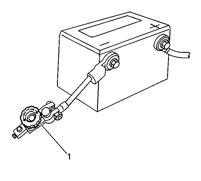
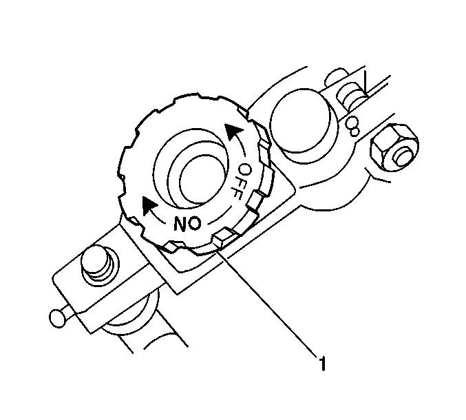
Important: The switch knob on the J 38758 is marked ON and OFF. When the switch knob is in the ON position, the circuit is closed and electrical current will pass through the switch. When the switch knob is in the OFF position, the circuit is open and electrical current will NOT pass through the switch.
- Disconnect the battery ground (negative) cable from the battery ground (negative) terminal. Refer to Battery Negative Cable Disconnection and Connection .
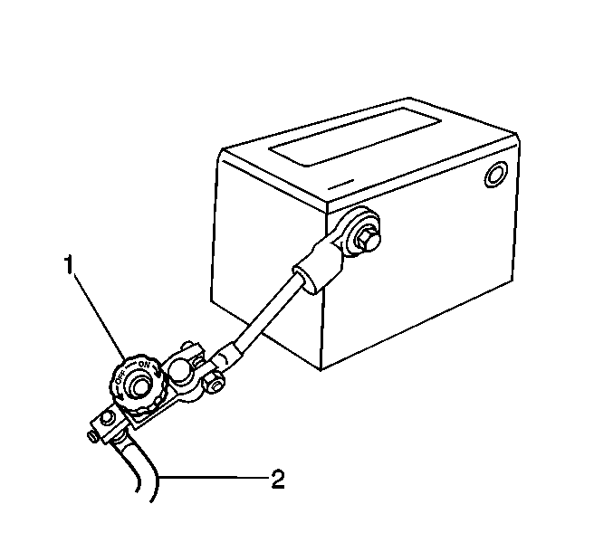
- Install the male end of the J 38758 to the battery ground (negative) terminal.
- Turn the J 38758 knob (1) to the OFF position.
- Install the battery ground (negative) cable (2) to the female end of the J 38758 .
- Turn the J 38758 knob (1) to the ON position.
- Road test the vehicle and activate all of the accessories, including the radio and the air conditioning.
- Park the vehicle. Turn the ignition OFF and remove the ignition key.
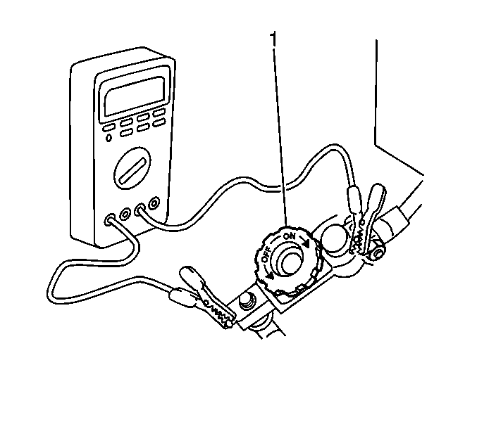
- Set the digital multimeter to the 10 ampere scale.
- Connect the digital multimeter to the J 38758 terminals.
- Turn the J 38758 knob (1) to the OFF position. The current flows through the digital multimeter.
- Slowly lower the hood while observing the underhood lamp (if applicable).
- Ensure that the interior lights are OFF and all the doors are closed.
- Wait at least one minute.
- Inspect and record the current reading. If the current reading is LESS than 2, perform the following steps.
- Wait 10 minutes.
- Inspect and record the current reading.
- Note the battery reserve capacity. Refer to Battery Usage .
- Divide the battery reserve capacity by 4. The resulting number indicates the maximum parasitic current (milliamperes) allowed by the battery.
- Compare the parasitic current reading in step 15 to the maximum parasitic current.
- Repeat the parasitic current drain test (as necessary) in order to ensure that the parasitic current drain is now BELOW the maximum parasitic current.
- Remove the J 38758 .
- Connect the battery ground (negative) cable to the battery ground (negative) terminal. Refer to Battery Negative Cable Disconnection and Connection .
Notice: Do not turn the parasitic draw test switch to the OFF position with the engine running. Damage will occur to the vehicle's electrical system.
| • | If the underhood lamp switches OFF while lowering the hood, it is working properly. Disconnect the underhood lamp. |
| • | If the underhood lamp does not switch OFF, the underhood lamp is most likely the source of the excessive parasitic current. |
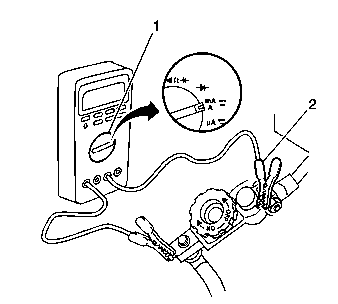
| 14.1. | Turn the J 38758 knob (1) to the ON position. Continuity is maintained in the electrical system. |
| 14.2. | Switch the digital multimeter to the 2 ampere scale in order to obtain a more accurate reading. |
| 14.3. | Turn the J 38758 knob to the OFF position. |
EXAMPLE: If the battery has a reserve capacity of 100 minutes, the maximum parasitic current allowed by the battery is 25 milliamperes.
| • | If the parasitic current reading does NOT exceed the calculated maximum parasitic current, the system is OK. |
| Notice: The test switch must be in the ON position when removing the fuses in order to maintain continuity in the electrical system. This avoids damaging the digital multimeter due to accidental overloading, such as a door being opened to change a fuse. |
| • | If the parasitic current reading EXCEEDS the maximum parasitic current, remove each fuse, one at a time, until the parasitic current drain is at or below the calculated maximum parasitic current. This process will help isolate the circuits which are causing the excessive parasitic current drain. Refer to Fuse Block Schematics in Wiring Systems and the following Parasitic Current Drain Table in order to determine which PART of the circuit (or component) is causing the excessive parasitic current drain. Repair the system as necessary. |
| Important: Sometimes a NON-FUSED circuit or component (generator) may cause excessive parasitic current drain. |
Component | Fuse | Current Draw | |
|---|---|---|---|
Typical | Maximum | ||
ECM | ECM SENSE | 0.4 mA | 1.0 mA |
ABS/TCS ECU | ABS MOD BATT (IP) | 0.3 mA | 1.0 mA |
Generator | -- | 0.7 mA | 1.0 mA |
Auto Level Control | ELC (IP) | 0.7 mA | 1.0 mA |
Body Computer (BCM) | PWR LOCK (IP) and/or CTSY LAMP (IP) | 1.2 mA | 2.0 mA |
Radio | RADIO (UH) | 3.0 mA | 6.9 mA |
Keyless Entry Module | RADIO (UH) | 2.0 mA | 3.0 mA |
Shock Sensor | RADIO (UH) | 1.4 mA | 2.0 mA |
HVAC Control Head | RADIO (UH) | 0.7 mA | 1.0 mA |
Power Sliding Door Module | RADIO (UH) | 0.9 mA | 1.0 mA |
