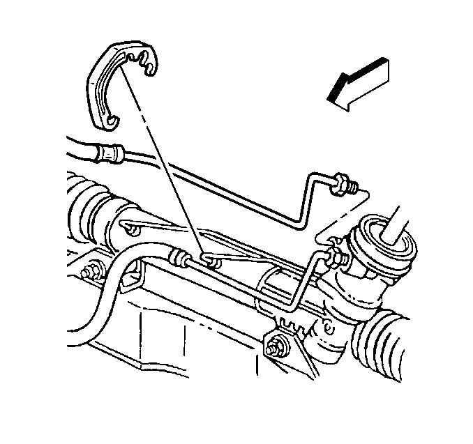
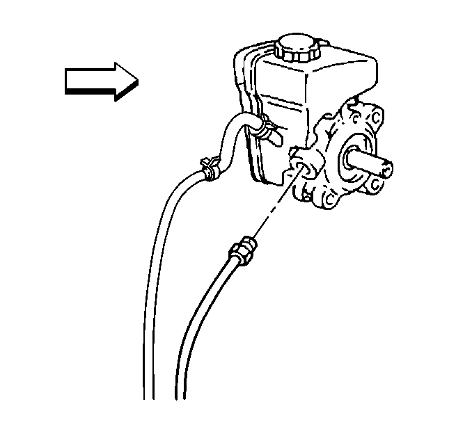
Removal Procedure
- Raise and support the vehicle. Refer to Lifting and Jacking the Vehicle in General Information.
- Remove the intermediate shaft from the steering gear. Refer to Lower/Upper Intermediate Steering Shaft Replacement in Steering Wheel and Column - Tilt.
- Use a utility stand in order to support the frame rear.
- Remove the frame rear bolts. Refer to Frame Replacement in Frame and Underbody.
- Use the utility stand in order to lower the frame rear to gain access.
- Remove the power steering gear heat shield. Refer to Steering Gear Heat Shield Replacement .
- Place the drain pan under the power steering pump and the power steering gear.
- Remove the power steering gear hose clip.
- Remove the inlet hose from the steering gear.
- Use the utility stand in order to raise the frame rear.
- Install the OLD frame bolts. Fully seat the frame bolts. Do NOT tighten the frame bolts.
- Lower the vehicle.
- Remove the drive belt. Refer to Drive Belt Replacement in Engine Mechanical - 3.4L.
- Remove the inlet hose from the pump.
- Remove the inlet hose from the hose retainer.
- Remove the inlet hose.
Caution: Failure to disconnect the intermediate shaft from the rack and pinion stub shaft can result in damage to the steering gear and/or intermediate shaft. This damage can cause loss of steering control which could result in personal injury.
Notice: When adding fluid or making a complete fluid change, always use the proper power steering fluid. Failure to use the proper fluid will cause hose and seal damage and fluid leaks.


Installation Procedure
- Install the inlet hose.
- Install the inlet hose to the pump.
- Install the inlet hose to the hose retainer.
- Install the drive belt. Refer to Drive Belt Replacement in Engine Mechanical - 3.4L.
- Raise and support the vehicle. Refer to Lifting and Jacking the Vehicle in General Information.
- Use a utility stand in order to support the frame rear.
- Remove and DISCARD the frame rear bolts.
- Use the utility stand in order to lower the frame rear to gain access.
- Install the inlet hose to the steering gear.
- Install the power steering gear hose clip.
- Install the power steering gear heat shield. Refer to Steering Gear Heat Shield Replacement .
- Use the utility stand in order to raise the frame rear.
- Install the NEW frame rear bolts. Refer to Frame Replacement in Frame and Underbody.
- Install the intermediate shaft to the steering gear. Refer to Lower/Upper Intermediate Steering Shaft Replacement in Steering Wheel and Column - Tilt.
- Lower the vehicle.
- Fill the power steering fluid reservoir. Refer to Fluid and Lubricant Recommendations in Maintenance and Lubrication.
- Bleed the power steering system. Refer to Power Steering System Bleeding .

Tighten
Tighten the power steering gear inlet hose fitting to 27 N·m
(20 lb ft).

Notice: Use the correct fastener in the correct location. Replacement fasteners must be the correct part number for that application. Fasteners requiring replacement or fasteners requiring the use of thread locking compound or sealant are identified in the service procedure. Do not use paints, lubricants, or corrosion inhibitors on fasteners or fastener joint surfaces unless specified. These coatings affect fastener torque and joint clamping force and may damage the fastener. Use the correct tightening sequence and specifications when installing fasteners in order to avoid damage to parts and systems.
Tighten
Tighten the power steering gear inlet hose fitting to 27 N·m
(20 lb ft).
Notice: Set steering shaft so the block tooth on the upper steering shaft is at the 12 o'clock position, the wheels on the vehicle are straight ahead and set the ignition switch to the LOCK position. Failure to follow these procedures could result in damage to the coil.
