Circuit Description
DTC C1344 detects a stuck TCS motor or a seized hydraulic modulator. During initialization or after a TCS cycle the EBCM/EBTCM commands the TCS motor in the reverse direction and the forward direction to ensure that the motor moves properly. If the TCS motor does not move the EBCM/EBTCM detects improper current feedback. A DTC will then set.
Conditions for Setting the DTC
DTC C1344 will set during initialization or after a TCS cycle. A malfunction exists if the EBCM/EBTCM detects a condition in which the EBCM/EBTCM cannot move the motor in either direction.
Action Taken When the DTC Sets
| • | A malfunction DTC stores. |
| • | The TCS disables. |
| • | The amber TCS indicator turns on. |
| • | The red BRAKE warning indicator turns on. |
Conditions for Clearing the DTC
| • | The condition responsible for setting the DTC no longer exists and the Scan Tool Clear DTC function is used. |
| • | 100 drive cycles pass with no DTC detected. |
Diagnostic Aids
An intermittent malfunction in DTC C1344 may be caused by one of the following conditions in a mechanical part of the system:
| • | Sticking |
| • | Binding |
| • | Slipping |
Use the enhanced diagnostic function of the Scan Tool in order to measure the frequency of the malfunction. Refer to the Scan Tool manual or Scan Tool Diagnostics located in this section for the procedure.
Thoroughly inspect any circuitry that may cause the intermittent complaint for the following conditions:
| • | Backed out terminals |
| • | Improper mating |
| • | Broken locks |
| • | Improperly formed or damaged terminals |
| • | Poor terminal-to-wiring connections |
| • | Physical damage to the wiring harness |
Important: Zero the J 39200 test leads before making any resistance measurements.
Step | Action | Value(s) | Yes | No | ||||||||
|---|---|---|---|---|---|---|---|---|---|---|---|---|
1 | Was the Diagnostic System Check performed? | -- | ||||||||||
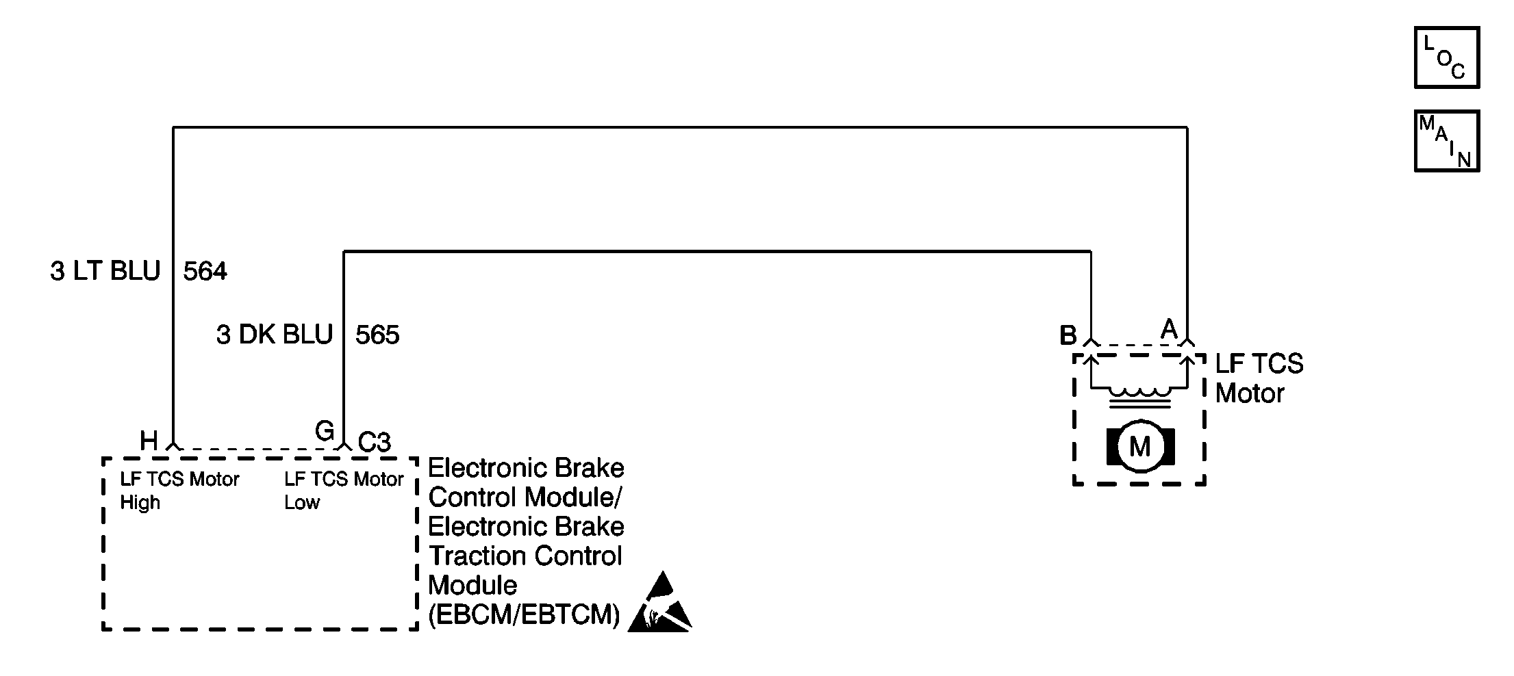
2 | Visually inspect the following components for proper wire color/connector cavity combination:
Are the proper wires located in the proper connector cavities? | -- | ||||||||||
3 |
Support the vehicle. Does the left front wheel rotate? | -- | ||||||||||
4 |
Does the left front wheel rotate? | -- | ||||||||||
5 |
Was the left front TCS motor feedback current within the specified current? | 7-9A | ||||||||||
6 |
Is continuity present during this test? | -- | ||||||||||
7 | Use the J 39200 in order to measure the resistance between the following components:
Is the resistance within the specified resistance? | 0.2-1.5 ohms | ||||||||||
8 | Inspect the following components for poor terminal contact or corrosion:
Do any of the terminals exhibit poor terminal contact or corrosion? | -- | ||||||||||
9 |
Does DTC C1344 set during the last three drive cycles? | -- | ||||||||||
10 |
(The hydraulic modulator gear is the furthest rearward gear when the TCS modulator is installed in the vehicle.) Can the hydraulic modulator gear be rotated at least seven full revolutions from lock to lock? | -- | ||||||||||
11 |
Is the repair complete? | -- | -- | |||||||||
12 | Repair the short between CKT 564 and CKT 565. Is the repair complete? | -- | -- | |||||||||
13 | Replace the TCS motor pack. Refer to Traction Control System Motor Pack Replacement . Is the repair complete? | -- | -- | |||||||||
14 | Replace the TCS modulator. Refer to Traction Control System Modulator Replacement . Is the repair complete? | -- | -- | |||||||||
15 | Replace the terminals that exhibit the following conditions:
Is the repair complete? | -- | -- | |||||||||
16 | Replace the EBCM/EBTCM. Refer to Electronic Brake and Traction Control Module Replacement . Is the repair complete? | -- | -- | |||||||||
17 | The malfunction is intermittent or not present at this time? Is a concern still present? | -- | Go to Diagnostic Aids |
