REAR DISC BRAKE CALIPERS INSTALL REVISED CONE ADJUSTER

Subject: REAR DISC BRAKE CALIPERS (INSTALL REVISED CONE-CLUTCH ADJUSTOR)
Models Affected: 1982-88 FIREBIRD, 1984-87 FIERO AND 1983-88 6000 STE
This bulletin is being revised to change the part number on the Seal Kit for the Fiero and 6000 STE. This bulletin cancels and replaces bulletin 88-5-19 issued 11/91. Please discard bulletin 88-5-19.
Condition:
--------- Some cases have been reported where the self-adjustors in the rear calipers do not function properly on 1982-88 Firebird, 1984-87 Fiero and 1983-88 6000 STE models equipped with automatic transmissions.
Correction:
---------- To correct this, a revised cone-clutch adjustor has been released.
Service Procedure:
A. Raise vehicle and remove rear tire/wheel assembly (or assemblies), per Service Manual.
B. Spray the equalizer and bleeder screw(s) with liquid wrench (or equivalent).
C. Remove rear caliper(s), per shop manual.
D. Remove pads.
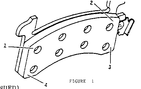
E. Inspect brake pads for taper wear or excessive wear. Taper wear can be determined by taking measurements at the four points shown in the diagram below.
Calculate pad taper by subtracting the thinnest point measured from the thickest point measured.
The brake pads should be replaced if taper is greater than .080 inches.
F. Overhaul caliper(s):
Tools Required:
J-22269-01 Piston Installer J-38898 New Boot Seal Installer
1. Remove bleeder screw.
Note: If excessive resistance is encountered, use the following procedure to prevent breakage:
(A). First put 10mm socket over bleeder screw and tap lightly on it.
(B). If step (A) does not help, use a propane torch to heat the caliper around bleeder screw after assuring that any excess liquid wrench has been removed from surface. Apply heat to caliper for approximately 30 seconds to 1 minute (maximum). DO NOT USE AN ACETYLENE TORCH. OVERHEATING THE ALUMINUM CALIPER COULD CAUSE THE BLEEDER SCREW TO STRIP ITS THREADS.
2. Remove shoe dampening spring from end of piston.
3. Remove park brake lever.
4. Remove lever seal and anti-friction washer.
5. Remove piston by turning actuator screw with lever or wrench.
6. Do not reuse old piston and balance spring.
7. Remove actuator screw by pressing on threaded end.
8. Remove shaft seal and thrust washer from actuator screw.
9. Remove old boot while being careful not to scratch the housing bore.
10. Remove piston seal, using a wood or plastic tool that won't damage the caliper bore.
11. Remove caliper mounting bolts, bushings, and sleeves.
12. Inspect caliper bore and seal groove. If necessary, use crocus cloth to polish out any light corrosion.
13. Clean:
o Clean all parts with GM Brake Parts Cleaner, P/N 12345754 (or equivalent).
o Dry with unlubricated compressed air.
o Blow out all passages in housing and bleeder screw.
14. First clean internal passage in bleeder screws, then reinstall bleeder screw and torque to 6-9 N.m (80-140 lbs. in.).
15. Install new piston seal. Lubricate seal and bore with brake fluid.
Note: Make sure seal is not twisted.
16. Install lubricated new boot onto NEW piston with inside lip of boot in piston groove and boot fold toward end of piston that contacts inboard brake pad.
17. Install thrust washer on actuator screw with copper side of washer towards the piston assembly and the gray surface towards the caliper housing.
18. Install lubricated shaft seal on actuator screw.
19. Install actuator screw into piston.
20. Install NEW balance spring into the piston recess.
21. Guide lubricated piston assembly into lubricated bore of caliper.
Note: Excessive force IS NOT required for installation. Do not allow piston to cock in bore, as seal will be damaged.
22. When resistance (seal engagement) is met, rotate the piston assembly back and forth to insure that it is square to the seal.
Note: Orient piston so pad notches are in vertical position.
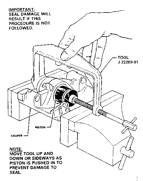
23. Use tool #J-22269-01 to install the piston through the piston seal. Shake the tool to align the piston to seal while gently turning the jack screw to push piston through the seal to the bottom of the caliper bore.
24. Install the lubricated anti-friction washer and lever seal over the end of actuator screw.
Note: The sealing bead on the lever seal should be against the housing.
25. Install the lever on the actuator screw. Rotate lever away from stop slightly and hold while installing nut to 48 N.m (35 lbs. ft.). Then rotate lever back to contact stop.
26. Seat boot into caliper housing counter bore using tool #J-38898.
27. Install new brake pad dampening spring in groove on end of piston .
o All Firebird models require a new spring, P/N 18019098.
o 1984 - 87 Fiero models require a new spring, P/N 18011729.
o 1983-88 6000 (STE) models use the same spring, P/N 18011729.
28. Clean, lubricate, and reinstall sleeves, bushings, and caliper mounting bolts.
29. Reinstall brake pads.
G. Reinstall caliper(s), per shop manual.
H. Install hydraulic fitting and bolt using 2 new brass washers, and torque to 33 N.m (24 lbs. ft.).
I. Bleed brake system as required (power or manual) per shop manual.
J. Apply approximately 778 N (175 lbs.) force 3 times to the brake pedal to seat the linings.
K. Clinch outboard shoe to caliper, per shop manual.
L. Readjust park brake cable, per shop manual.
M. Reinstall wheel(s) and tire(s), per shop manual.
Parts List
Service Kit FIREBIRD FIERO AND 6000 STE -------- ------------------ Actuator Asm. 18019241 18019241 (LH) (Includes balance spring) 18019242 (RH)
Seal Kit 18019240 18019240
Brake Hose Washer 10139097 10139097 (2 Required)
Shoe Retaining Spring 18019098 18011729
Parts are currently available from GMSPO.
Labor Operation Number: T1774
Labor Time 6000 - 1.4 Hours per one caliper 6000 - 1.9 Hours per two calipers Fiero 1.4 Hours per one calipers Firebird l.4 Hours per one calipers Fiero 1.9 Hours per two calipers Firebird 2.0 Hours per two calipers
Parts are currently available from GMSPO.


General Motors bulletins are intended for use by professional technicians, not a "do-it-yourselfer". They are written to inform those technicians of conditions that may occur on some vehicles, or to provide information that could assist in the proper service of a vehicle. Properly trained technicians have the equipment, tools, safety instructions and know-how to do a job properly and safely. If a condition is described, do not assume that the bulletin applies to your vehicle, or that your vehicle will have that condition. See a General Motors dealer servicing your brand of General Motors vehicle for information on whether your vehicle may benefit from the information.
