RACK/PINION POWER STEERING VALVE RING SERVICE

VEHICLES AFFECTED: 1982-1984 A-X-J Series Equipped With Power Steering
1. Valve Ring Information and Service
Orange colour valve rings have been phased into 1984 production, replacing the green rings. The present green ring service kit part number 7840573 may be used to replace orange rings as they are interchangeable.
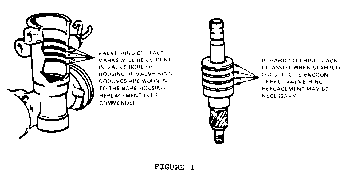
The design intent is that valve rings will remain stationary in the bore of a power rack & pinion assembly. If hard steering, lack of assist when started cold, etc., is enrountered with normal pump pressure, inspect the rack & pinion housing valve bore. See Fig.
Ring contact marks in the valve bore is normal. If ring groove wear exists, replacement of the housing is necessary to assure that replacement rings will not eventually wear further into the housing and result in a recurrence of a lack of power assist symptom.
If only one or two of the four ring contact marks in the housing have resulted in ring groove wear, the corresponding ring land of the valve is most likely causing excessive ring drag.
Inspect valve ring land for any imperfection or burr which may restrict ring rotation. Remove any burrs with a hone. If replacement rings will not rotate freely on the valve, valve replacement is required.
In mid-year 1984, the rack & pinion housing valve bore will have a textured finish to further insure valve ring retention to the bore. The textured area in the bore will be the circular band sealing ring surface corresponding to the four rings in the valve body.
NOTE: 1980-81 'X' Series power rack & pinion assemblies are to be serviced as instructed in the 1981 Product Service Bulletin 90-108 and 1983 F.S.B. (Special Policy) 3-109.
Service precuation on removal of valve and pinion assembly:
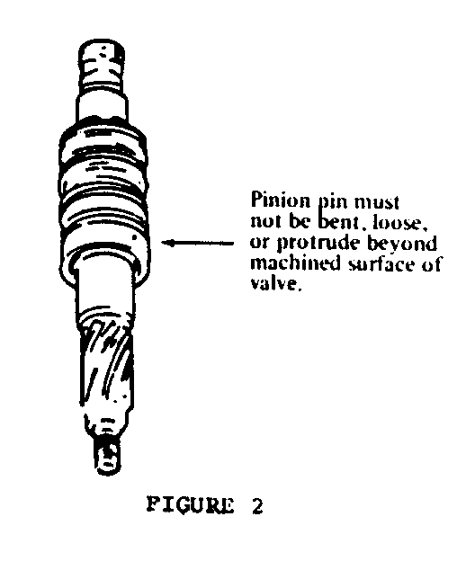
The appropriate Service Manuals list the procedure for valve removal and valve ring replacement. The valve must be pressed out of the housing per the manual procedure. Excessive force or hammer use will likely damage the valve or valve pinion pin. After valve removal inspect the valve pinion pin for being loose, bent, or protruding beyond the valve machines surfaces. See Fig. If any of these conditions exist, valve body replacement is required.
2. Rack Piston Information and Service
A lack of power assist symptom may also be caused by leakage past the rack piston ring in the housing tube bore. Inspect the rack piston ring for damage or distortion. The piston ring to ring land side clearance should not exceed .20mm (.008 inches). Also inspect the housing tube bore for any nicks, scoring or other imperfection in the rack piston travel area.
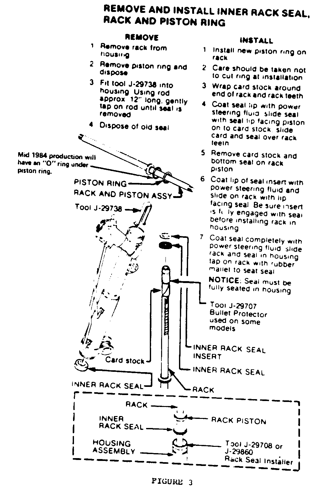
Mid 1984 production will have an 'O' ring under the piston to expand the ring against the housing for improved ring-to-housing bore sealing. See Figure 3.
We have heard of some rack and pinion gear seal leakage after the inner rack seal was replaced. Some causes may be: water damage to the piston rod from water intrusion past housing drive screw, refer to 3 3-101 dated Oct. 31/83, lack of cleaning burrs from retaining ring groove, not using rack seal bullet protector, or not properly protecting the inner rack seal from the rack teeth during installation. Protect the seal by sliding seal onto card stock, and then slide card stock and seal down the rack teeth. See Figure 3.


General Motors bulletins are intended for use by professional technicians, not a "do-it-yourselfer". They are written to inform those technicians of conditions that may occur on some vehicles, or to provide information that could assist in the proper service of a vehicle. Properly trained technicians have the equipment, tools, safety instructions and know-how to do a job properly and safely. If a condition is described, do not assume that the bulletin applies to your vehicle, or that your vehicle will have that condition. See a General Motors dealer servicing your brand of General Motors vehicle for information on whether your vehicle may benefit from the information.
