VAC. THROTTLE KICKER SOLENOID SERVICE MANUAL REVISION

IDLE SPEED ACTUATOR (THROTTLE KICKER) CIRCUIT OPERATION ON 2.8L V-6 (VIN CODE X) ENGINE 1986 PONTIAC 6000 MODELS
This bulletin is being revised to provide additional general information and circuit theory on the throttle kicker operation. Also the artwork has been revised to eliminate the reference to police only on the chart.
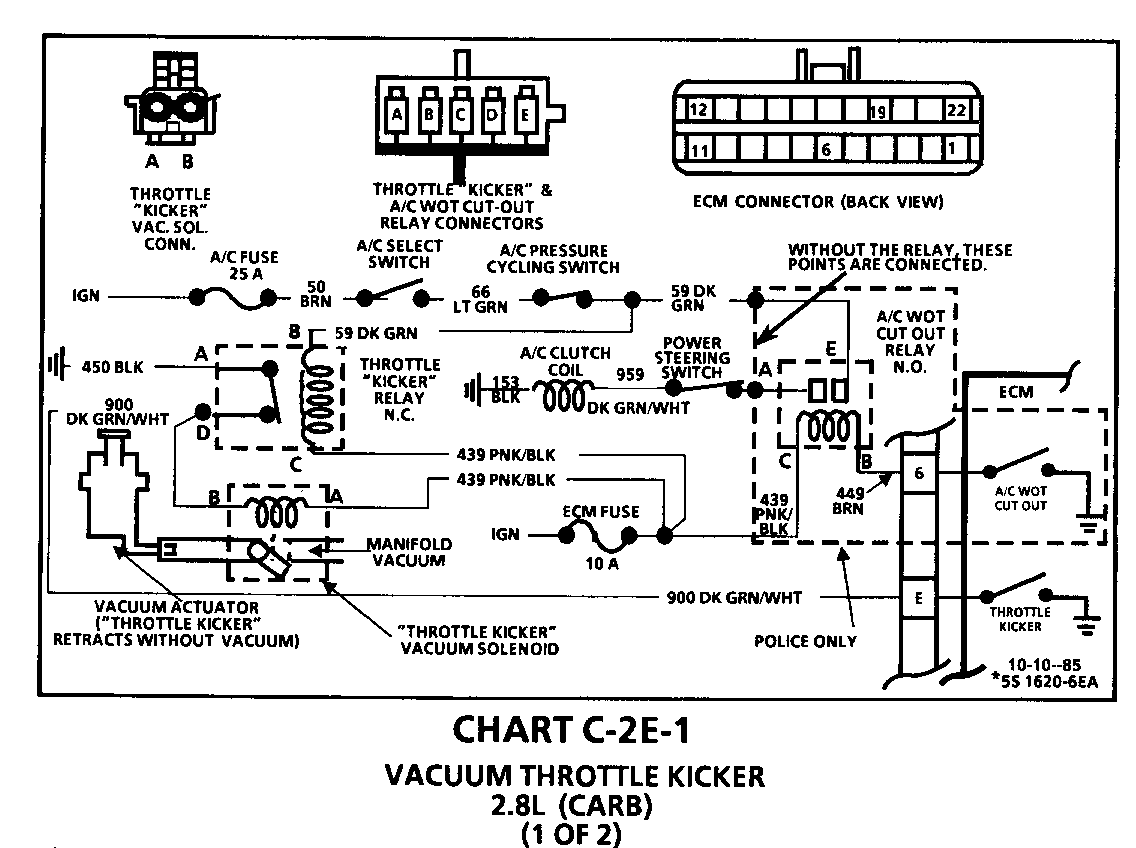
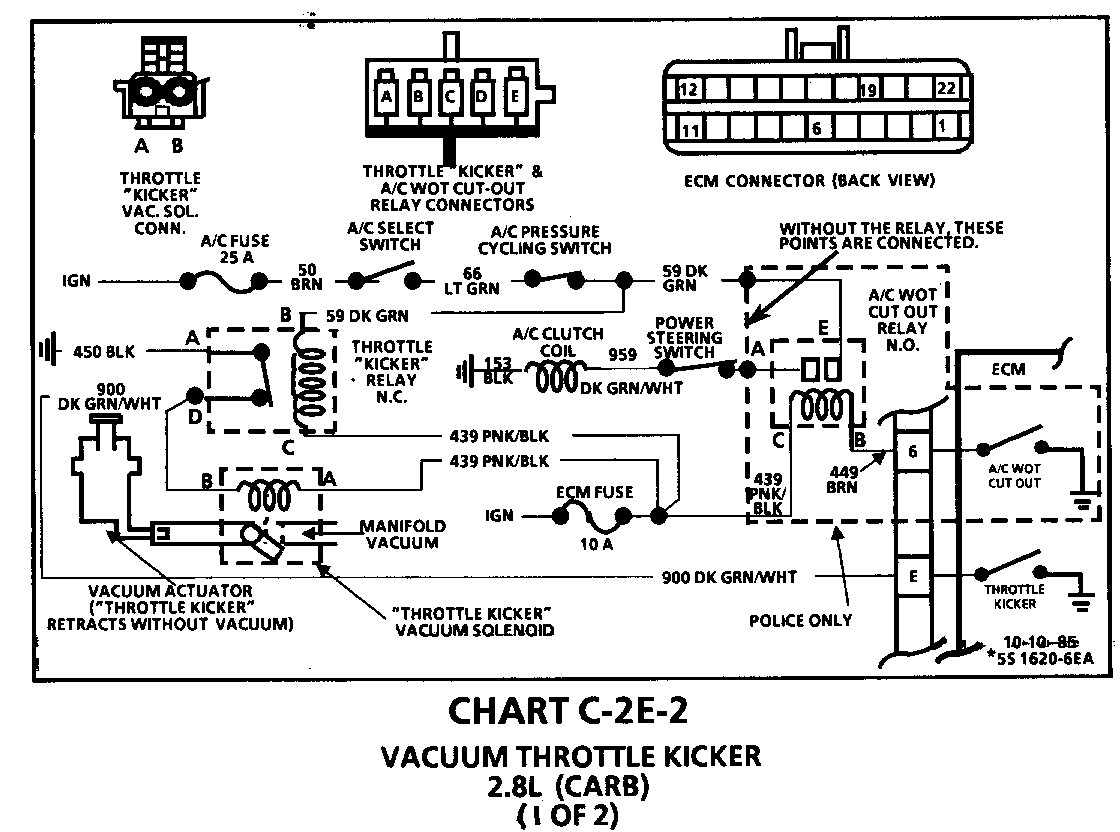
Chart C-2E-1 on page 6E1-C2-13 in the 6000 Service Manual and the electrical schematic on page 63-4 in Section 8A in the 1986 chassis Service Manual have been revised.
Please update the above pages in your respective service manuals with the revised information in this bulletin.
I. Circuit Operation - General Description
The E2SE carburetors use a Vacuum Operated Idle Speed Actuator (throttle kicker) that is mounted on the carburetor. The idle speed actuator plunger is normally retracted (throttle not held open by plunger). Vacuum to the idle speed actuator is controlled by an idle speed actuator vacuum solenoid. The vacuum solenoid is energized two ways:
1. ECM control - energizes vacuum solenoid:
a. When engine coolant is below 85 degrees Celsius (185 degrees Fahrenheit).
b. For 30 seconds after every engine start up, if coolant is above 85 degrees Celsius (185 degrees Fahrenheit).
c. On engine deceleration, using a calibrated TPS and RPM value to allow a greater throttle opening for improved emissions.
2. Vacuum Solenoid relay control-energizes the vacuum solenoid:
a. When A/C control head is in MAX, NORM, BI-Level, or DEF position, if A/C pressure cycling switch is closed.
b. When power steering cut out switch is open (high P/S line pressure).
The vacuum solenoid is normally open (no vacuum through to idle speed actuator) and the vacuum solenoid relay is normally closed.
II. Circuit Operation - Theory ------------------------------ The Idle Speed Actuator (throttle kicker) is used to control idle speed as commanded by the ECM and/or vacuum solenoid relay (throttle kicker relay).
Inputs to the ECM are distributor reference, TPS, RPM, and coolant temperature. Inputs to the vacuum solenoid relay are A/C on signal and the power steering cut out switch status.
The ECM and/or vacuum solenoid relay control the vacuum solenoid valve and the vacuum solenoid valve controls the idle speed actuator, which controls idle speed.
When the engine is started, the ECM grounds the vacuum solenoid causing the solenoid valve to close (vacuum passes through to idle speed actuator) thereby causing the idle speed actuator to extend and increase idle speed. The ECM keeps the vacuum solenoid grounded (closed) for 30 seconds after the first distributor reference pulse is received or until the coolant temperature reaches 85 degrees C (185 degrees F), whichever occurs last. The ECM will also ground the vacuum solenoid during engine deceleration, using a calibrated TPS and RPM value, to allow a greater throttle opening for improved emissions.
Independent of ECM control over the idle speed actuator and vacuum solenoid is the vacuum solenoid relay.
The vacuum solenoid relay energizes the idle speed actuator and vacuum solenoid by providing an auxiliary ground path for the vacuum solenoid. The vacuum solenoid relay de-energizes the idle speed actuator and vacuum solenoid by opening and interrupting the ground circuit for the vacuum solenoid (assuming the ECM is not grounding the vacuum solenoid).
The vacuum solenoid relay is normally closed, de-energized, and opens when energized. The vacuum solenoid relay may be de-energized when the ignition is on by:
1. Turning A/C control to max, norm, bi-level or def position (A/C pressuring cycling switch closed). This allows system voltage to both sides of the relay coil.
2. The power steering cutout switch opening during high P/S line pressure. With the A/C off, this interrupts the ground circuit for the relay coil.
The vacuum solenoid relay is energized (when the ignition is on), when the A/C is off and the power steering pressure switch is closed. (Note: With the A/C off, it is assumed that the A/C high pressure cut off switch is closed.)
The resistance of the vacuum solenoid relay coil is high and the resistance of the A/C compressor clutch coil is low. Therefore, when the vacuum solenoid relay is energized (A/C off) the voltage drop across the A/C compressor clutch coil is low and is not sufficient to engage the clutch. The A/C clutch coil also provides a good path for the vacuum solenoid relay coil, due to its low resistance.
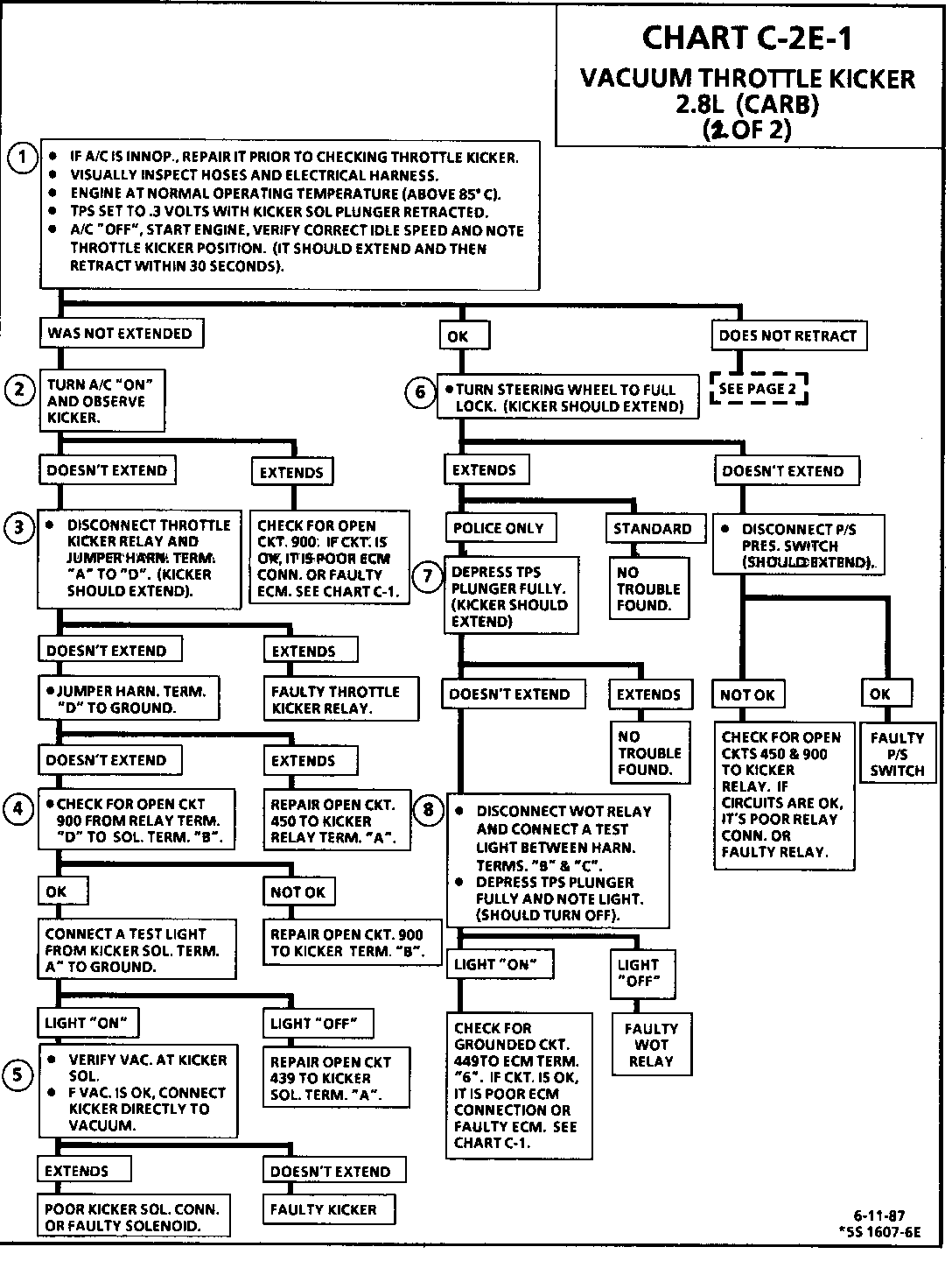
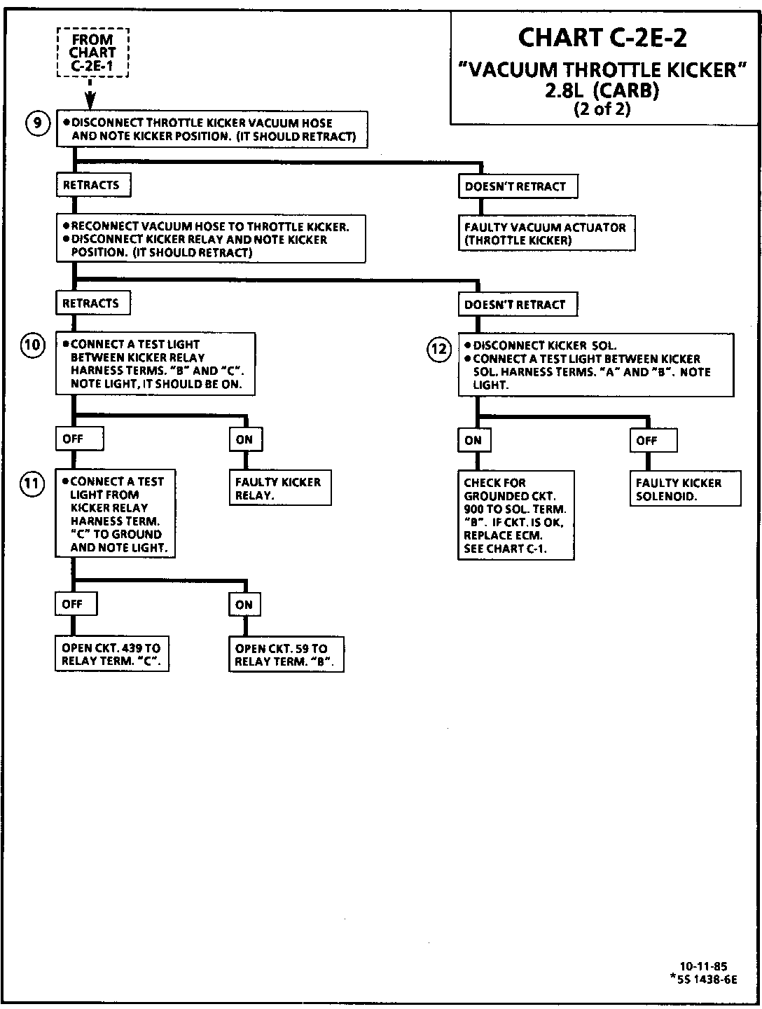
CHART C-2E-1 VACUUM THROTTLE KICKER 2.8L CARBURETED
CIRCUIT DESCRIPTION:
"Throttle Kicker" is vacuum operated and extends under the following conditions:
o Coolant temperature below 85 deg Celsius (185 deg Fahrenheit).
o For 30 seconds after start if coolant temperature above 85 deg Celsius (185 deg Fahrenheit).
o A/C "ON" and pressure cycling switch closed (clutch "ON").
o Full turn (power steering switch open).
TEST DESCRIPTION
Numbers below refer to circled numbers on diagnosis chart.
1. Checks ECM control of kicker solenoid and for an open in kicker relay coil circuit. TPS should be 30 volts with kicker solenoid plunger retracted and idle speed set to specifications. If TPS and idle speed are above specification, the ECM will energize the kicker solenoid.
2. Checks for open kicker solenoid coil circuit to ECM.
3. Checks for faulty throttle kicker relay.
4. Checks for open CKT 900 between kicker solenoid and relay.
5. Checks vacuum source to solenoid, then checks for faulty kicker.
6. Checks to see that power steering switch opens, and the kicker relay contact circuit is not open.


General Motors bulletins are intended for use by professional technicians, not a "do-it-yourselfer". They are written to inform those technicians of conditions that may occur on some vehicles, or to provide information that could assist in the proper service of a vehicle. Properly trained technicians have the equipment, tools, safety instructions and know-how to do a job properly and safely. If a condition is described, do not assume that the bulletin applies to your vehicle, or that your vehicle will have that condition. See a General Motors dealer servicing your brand of General Motors vehicle for information on whether your vehicle may benefit from the information.
