REPLACEMENT PAGES 1986 SERVICE MANUALS

VEHICLES AFFECTED: 6000, Grand Am and Sunbird Models
In the 1986 6000, Grand Am and Sunbird Service Manuals, pleast use the attached pages when referencing the following page numbers:
6E2-A-46 - 6000 6E2-A-46 - Grand Am 6E2-A-46 - Sunbird 6E2-A-50 - Sunbird 6E3-C3-4 - Grand Am 6E3-C3-5 - Grand Am
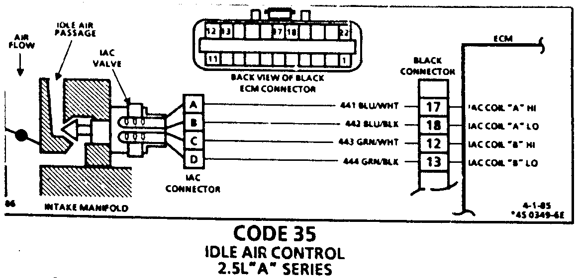
CODE 35 IDLE AIR CONTROL 2.5L "A" SERIES
Code 35 will set when the closed throttle engine speed is 50 RPM above or below the correct idle speed for 30 seconds. Review general discription in Section "C".
Following are nominal warm engine idle speeds:
AUTO MANUAL ALDL ---- ------ ---- Neutral 900 +/- 50 900 +/- 50 1000 +/- 50 Drive 800 +/- 50 1000 +/- 50
Continue with test even if engine will not idle. If idle is too low, "Scan" will display 80 or more counts, or steps. If idle is high and a visual check of the idle air passage shows a seated valve, locate and correct a vacuum leak.
If the idle is very high, usually above 1400 RPM and the IAC valve is not visible in the air passage, follow the left side of chart.
Occasionally an erratic or unstable idle may occur. Engine speed may vary 200 RPM or more up and down. disconnect IAC. If the condition is unchanged, the IAC is not at fault. There is a system problem. Proceed to paragraph three below.
When the engine was stopped, the IAC valve retracted (more air) to a fixed "Park" position to provide increased air flow during the next engine start. A "Scan" will display 95 or more counts and the valve should not be visible in the idle air passage.
Disconnecting the IAC will hold the valve in a retracted or open position and cause a closed throttle idle speed above 1500 RPM.
A "Scan" will now display "0" counts because the ECM has tried to reduce the idle speed by extending the valve. The IAC is OK. The code 35 is likely a thermac or cruise control vacuum hose disconnect.
A slow unstable idle may be caused by a system problem that cannot be overcome by the IAC. If the IAC is visible in the air passage the chart should locate the problem. If the valve is not visible the IAC is probably OK. In both cases the "Scan" counts will be above 60 counts.
System too lean (High Air/fuel ratio) Idle speed may be too h!gh or too low. Engine speed may vary up and down, disconnecting IAC does not help. May set Code 44.
"Scan" and/or Voltmeter will read an oxygen sensor output fixed at less than 300 mv (.3 v). Check for low regulated fuel pressure, water in fuel or lean injector. A lean exhaust with an oxygen sensor output fixed above 800 mv (.8 mv) will be a contaminated sennsor. usually silicone. This may also set a Code 45.
System too rich (Low air/fuel ratio) Idle speed too low. IAC valve not visible in idle air passage and "Scan" counts usually above 80. System obviously rich and may exhibit black smoke exhaust.
"Scan" tool and/or Voltmeter will read an oxygen sensor signal fixed above 800 MV (.8V).
Checks:
High fuel pressure
Leaking TBI injector "O" rings or injector. Ignition on, engine stopped. Using a fused jumper, connect 12 volts to fuel pump "test" terminal to pressurize system. Visually check for fuel dripping into manifold.
Rich injector.
Throttle Body. Remove IAC and inspect bore for foreign material or evidence of IAC valve dragging the bore.
Additional checks, see "Incorrect Idle" symptoms in Section "B".
Code 35 with A/C "on" check A/C compressor or relay diagnostic Chart C-10.
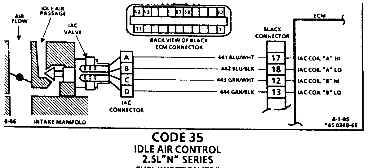
CODE 35 IDLE AIR CONTROL 2.5L "N" SERIES FUEL INJECTION (TBI)
Code 35 will set when the closed throttle engine speed is 50 RPM above or below the correct idle speed for 30 seconds. Review general discription in Section "C".
Following are nominal warm engine idle speeds:
AUTO MANUAL ALDL
Neutral 900 +/- 50 900 +/- 50 1000 +/- 50 Drive 800 +/- 50 1000 +/- 50
Continue with test even if engine will not idle. If idle is too low,"Scan" will display 80 or more counts or steps. If idle is high and a visual check of the idle air passage shows a seated valve, locate and correct a vacuum leak.
If the idle is very high, usually above 1400 RPM and the IAC valve is not visible in the air passage, follow the left side of chart.
Occasionally an erratic or unstable idle may occur. Engine speed may vary 200 RPM or more up and down. Disconnect IAC. If the condition is unchanged, the IAC is not at fault. There is a system problem. Proceed to paragraph three below.
When the engine was stopped, the IAV Valve retracted (more air) to a fixed "Park" position to provide increased air flow during the next engine start. A "Scan" will display 95 or more counts and the valve should not be visible in the idle air passage.
Disconnecting the IAC will hold the valve in a retracted or pen position and cause a closed throttle idle speed above 1500 RPM.
A "Scan" will now display "0" counts because the ECM has tried to reduce the idle speed by extending the valve. The IAC is OK. The code 35 is likely a thermac or cruise control vacuum hose disconnect.
A slow unstable idle may be caused by a system problem that cannot be overcoe by the IAC. If the IAC is visible in the air passage the chart should locate the problem. If the valve is not visible the IAC is probably OK. In both cases the "Scan" counts will be above 60 counts.
System too lean (High Air/fuel ratio) Idle speed may be too high or too low. Engine speed may vary up and down, disconnecting IAC does not help. May set Code 44.
"Scan" and/or Voltmeter will read an oxygen sensor output fixed at less than 300 mv (.3 v). Check for low regulated fuel pressure, water in fuel or lean injector. A lean exhaust with an oxygen sensor output fixed above 800 mV (.8 mv) will be a contaminated sensor, usually silicone. This may also set a Code 45.
System too rich (Low Air/fuel ratio) Idle speed too low. IAC valve not visible in idle air passage and "Scan" counts usually above 80. System obviously rich and may exhibit black smoke exhaust.
"Scan" tool and/or Voltmeter will read an oxygen sensor signal fixed above 800 mv (.8 v).
Check:
High fuel pressure
Leaking TBI injector "O" rings or injector. Ignition on, engine stopped.
Using a fused jumper, connect 12 volts to fuel pump "test" terminal to pressurize system. Visually check for fuel dripping into manifold.
Rich injector.
Throttle body. Remove IAC and inspect bore for foreign material or evidence of IAC valve dragging the bore.
Additional checks, see "Incorrect Idle" symptoms in Section "B".
Code 35 with A/C "on" check A/C compressor or relay diagnositcChart C-10.
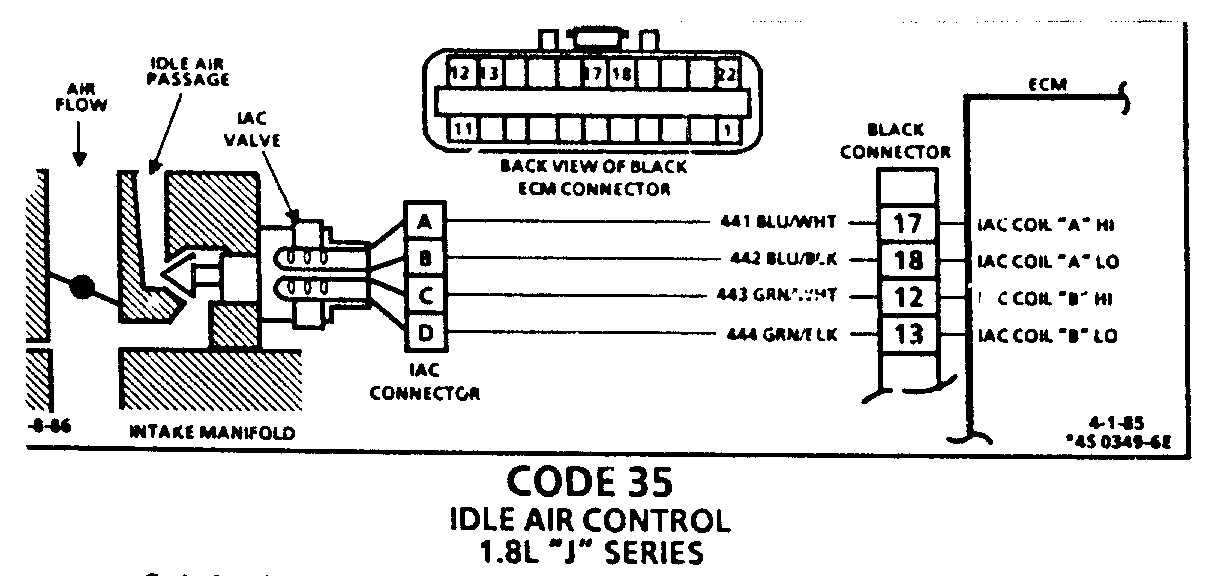
CODE 35 IDLE AIR CONTROL 1.8L "J" SERIES
Code 35 will set when the closed throttle engine speed is 50 RPM above or below the correct idle speed for 30 seconds. Review general description in Section "C".
Following are nominal warm engine idle speeds:
AUTO MANUAL ALDL
Neutral 900 +/- 50 900 +/- 50 1000 +/- 50 Drive 800 +/- 50 1000 +/- k50
Continue with test even if engine will not idle. If idle is too low, "Scan" will display 80 or more counts, or steps. If idle is high and a visual check of the idle air passage shows a seated valve, locate and correct a vacuum leak.
If the idle is very high, usually above 1400 RPM and the IAC valve is not visible in the air passage, follow the left side of chart.
Occasionally an erratic or unstable idle may occur. Engine speed may vary 200 RPM or more up and down. Disconnect IAC. If the condition is unchanged, the IAC is not at fault. There is a system problem. Proceed to paragraph three below.
When the engine was stopped, the IAC Valve retracted (more air) to a fixed "Park" position to provide increased air flow during the next engine start. A "Scan" will display 95 or more counts and the valve should not be visible in the idle air passage.
Disconnecting the IAC will hold the valve in a retracted or open position and cause a closed throttle idle speed above 1500 RPM.
A "Scan" will now display "0" counts because the ECM has tried to reduce the idle speed by extending the valve. The IAC is OK. The code 35 is likely a thermac or cruise control vacuum hose disconnect.
A slow unstable idle may be caused by a system problem that cannot be overcome by the IAC. If the IAC is visible in the air passage the chart should locate the problem. If the valve is not visible the IAC is probably OK. In both cases the "Scan" counts will be above 60 counts.
System too lean (High Air/fuel ratio)
Idle speed may be too high or too low. Engine speed may vary up and down, disconnecting IAC does not help. May set Code 44.
"Scan" and/or Voltmeter will read an oxygen sensor output fixed at less than 300 mv (.3v). Check for low regulated fuel pressure, water in fuel or lean injector. A lean exhaust with an oxygen sensor output fixed above 800 mV (.8mv) will be contaminated sensor, usually silicone. This may also set a Code 45.
System too rich (Low Air/fuel ratio)
Idle speed too low. IAC valve not visible in idle air passage and "Scan" counts usually above 80. System obviously rich and may exhibit black smoke exhaust.
"Scan" tool and/or Voltmeter will read an oxygen sensor signal fixed above 800 mv (.8 v). Check:
High fuel pressure
Leaking TBI injector "O" rings or injector. Ignition on, engine stopped. Using a fused jumper, connect 12 volts to fuel pump "test" terminal to pressurize system. Visually check for fuel dripping into manifold.
Rich injector
Throttle body. Remove IAC and inspect bore for foreign material or evidence of IAC valve dragging the bore.
Additional checks, see "Incorrect Idle" symptoms in Section "B".
Code 35 with A/C "on"; Check A/C compressor or relay diagnostic Chart C-10.
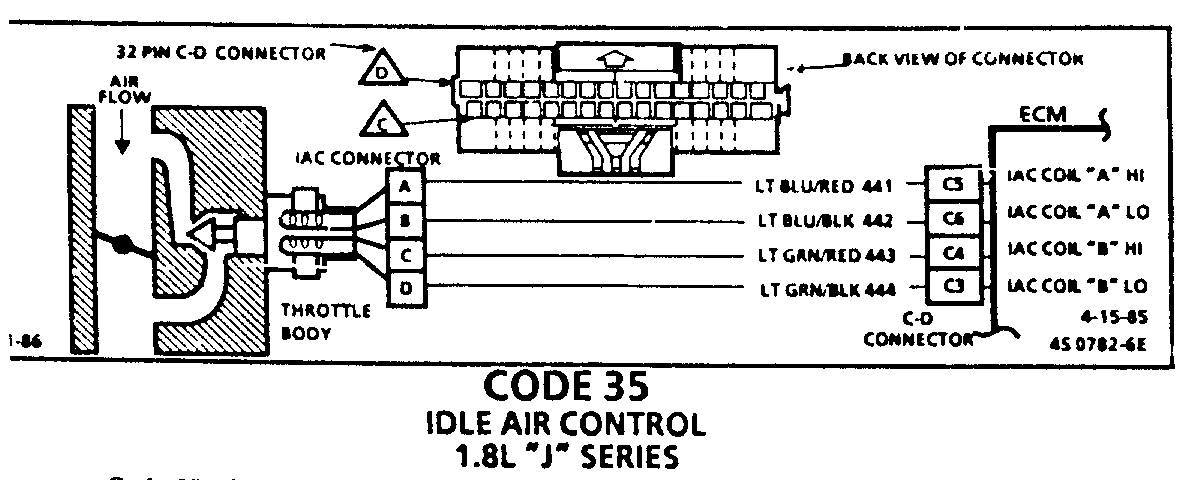
CODE 35 IDLE AIR CONTROL 1.8L "J" SERIES
Code 35 will set when the closed throttle engine speed is 150 RPM above or below the correct idle speed for 30 seconds. Review general discription in Section "C".
Following are nominal warm engine idle speeds:
AUTO MANUAL ALDL
Neutral 900 +/- 50 950 +/- 50 1000 +/- 50 Drive 825 +/- 50 1000 +/- 50
Continue with test even if engine will not idle. If idle is too low, "Scan" will display 80 or more counts, or steps. If idle is high it will display "O" counts.
Occasionally an erratic or unstable idle may occur. Engine speed may vary 200 rpm or more up and down. Disconnect IAC. If the condition is unchanged, the IAC is not at fault. There is a system problem. Proceed to paragraph three below.
When the engine was stopped, the IAC Valve retracted (more air) to a fixed "Park" position for increased air flow during the next engine start. A "Scan" will display 90 or more counts.
Disconnecting the IAC will hold the vlave in a retracted or open position and cause a closed throttle idle speed above 1500 rpm.
A "Scan" will now display "0" counts because the ECM has tried to reduce the idle speed by extending the valve. The IAC is OK. The code 35 id likely a CCP or cruise control vacuum hose disconnect.
A slow unstable idle may be caused by a system problem that cannot be overcome by the IAC. "Scan" counts will be above 60 counts if too low and "O" counts if too high.
If idle is too high, stop engine. Ignition on. Around diagnostic terminal. Wait a few seconds for IAC to seat then disconnect IAC. Start engine. If idle speed is above 800 +/- 30 rpm, locate and correct vacuum leak. System too lean (High Air/fuel ratio)
Idle speed may be too high or too low. Engine speed may vary up and down, disconnecting IAC does not help. May set Code 44.
"Scan" and/or Voltmeter will read an oxygen sensor output less than 300 MV (.3v.) Check for low regulated fuel pressure or water in fuel. A lean exhaust with an oxygen sensor output fixed above 800 mv (.8 mv) will be a contaminated sensor, usually silicone. This may also set a code 45.
System too rich (Low Air/Fuel Ratio)
Idle speed too low. "Scan" counts usually above 80. System obviously rich and may exhibit black smoke exhaust.
"Scan" tool and/or Voltmeter will read an oxygen sensor signal fixed above 800 MV (.8V). Check:
High fuel pressure
Injector leaking or sticking
Map sensor. Ignition on, engine stopped. Compare MAP Signal voltage with a known good vehicle with the same sensor. Voltage should be the same +/- 400 mv (.4 v). Also, disconnect MAP Sensor electrical connector. If idle improves, substitute a known good sensor recheck.
Throttle body. Removal IAC and inspect bore for foreign material or evidence of IAC valve dragging the bore.
A/C Compressor or relay failure. See Chart C-10.
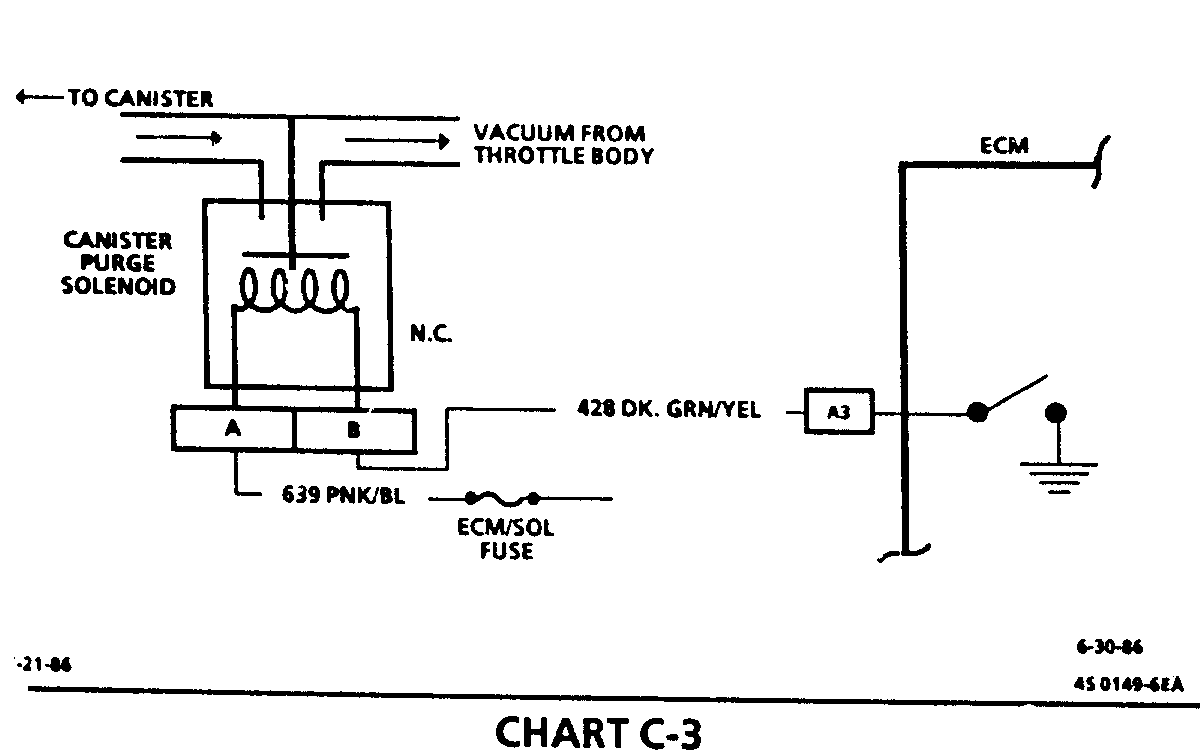
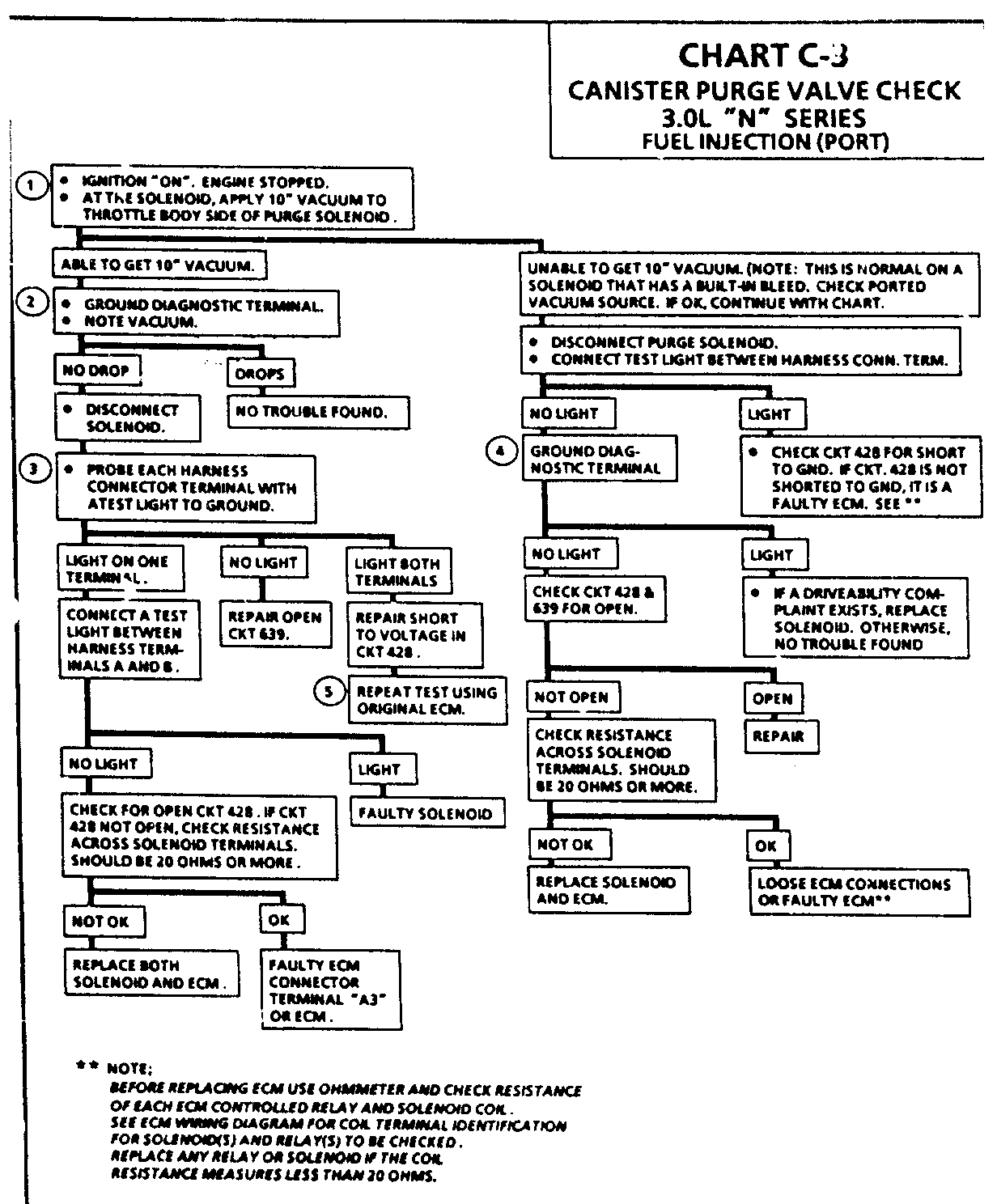
CHART C-3 CANISTER PURGE VALVE CH 3.0L "N" SERIES FUEL INJECTION (PORT) Circuit Description:
Canister purge is controlled by a solenoid that allows manifold vacuum to purge the canister when energized. The ECM supplies a ground to energize the solenoid (purge "ON").
If the diagnositc test terminal is grounded with the engine stopped or the following is met with the engine running the purge solenoid is energized (purge "ON").
Engine run time after start more than 1 minute.
Coolant temperature above 80 deg C (176 deg F).
Vehicle speed above 5 mph (8 km/h).
Throttle off idle. TPS signal above .75 volt.
Test Description: Step numbers refer to step numbers on diagnostic chart.
Checks to see if the solenoid is opened or closed.
The solenoid is normally de-energized in this step, so it should be closed.
Completes functional check by grounding test terminal. This should normally energize the solenoid and allow the vacuum to drop (purge "ON").
Checks for open or shorted solenoid circuit.
Checks to see if ECM control circuit or solenoid is at fault.
Solenoid coil resistance must measure more than 20 ohms. Less resistance will cause early failure of the ECM. Using an ohmmeter, check the purge solenoid, coolant fan relay resistance before install ing a replacement ECM, because they could cause failure of the purge circuit.
Checks to see if short to voltage damaged original ECM.
General Motors bulletins are intended for use by professional technicians, not a "do-it-yourselfer". They are written to inform those technicians of conditions that may occur on some vehicles, or to provide information that could assist in the proper service of a vehicle. Properly trained technicians have the equipment, tools, safety instructions and know-how to do a job properly and safely. If a condition is described, do not assume that the bulletin applies to your vehicle, or that your vehicle will have that condition. See a General Motors dealer servicing your brand of General Motors vehicle for information on whether your vehicle may benefit from the information.
