BROKEN CYLINDER HEAD BOLT COOLANT LOSS (NEW BOLT/GASKET)

VEHICLES AFFECTED: 1985-87 A/F/N/P/X CARS, S/T TRUCKS AND M VANS W/2.5L
This bulletin is being revised to include a procedure (in step 12) to be used if tool J36660 is unavailable. Two figures (5 and 6) have been added with respect to the additional procedure.
Major Tools Required:
Reversible Electric drill J-24460 and J-23699 Coolant System Pressure Tester J-36660 Torque-Angle Wrench J-38188 Head Bolt Kit: J-38188-1 Cylinder Head Bolt Extractor J-38188-2 3/16" Drill Guide J-38188-3 3/16" Drill Bit J-38188-4 Centre Drill Guide J-38188-2 3/16" Drill Guide J-38188-5 Centre Drill Bit
The following passenger cars, trucks, and vans equipped with the 2.5L engine may experience coolant loss due to broken cylinder head bolts:
1985-87 A-cars with 2.5L engine (VIN Code R) 1985-86 F-cars with 2.5L engine (VIN Code 2) 1985-87 N-cars with 2.5L engine (VIN Code U) 1985-87 P-cars with 2.5L engine (VIN Code R) 1985 X-cars with 2.5L engine (VIN Code R) 1985-87 S/T-trucks and M-vans with 2.5L engine (VIN Code E)
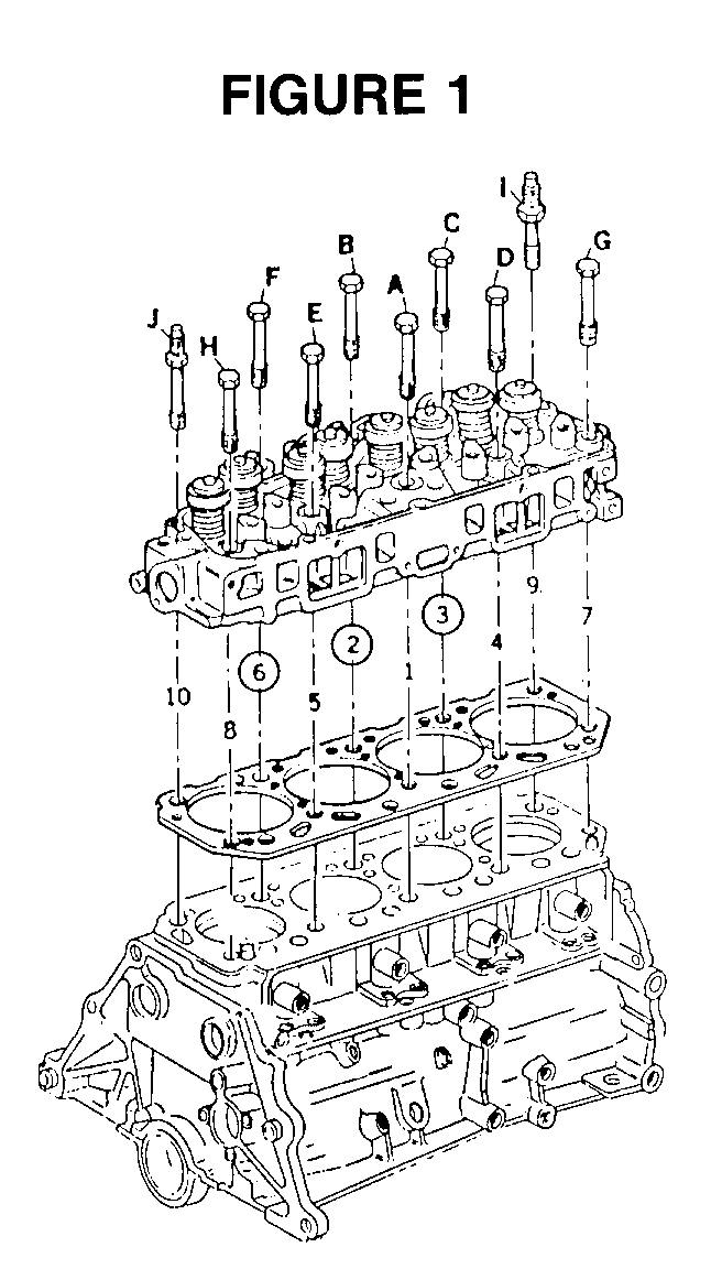
The head bolts most susceptible to this condition are the centre three located closest to the exhaust manifold, i.e. bolts #2, #3, and #6, see FIGURE 1. If one of these three bolts is broken, replace all 3 bolts with new ones per the Application Table.
The portion of the unbroken bolt remaining in the cylinder block may be extracted without removing the cylinder head. The procedure for extracting any broken head bolt is as follows:
Procedure:
---------- 1. Remove the top portion of the broken bolt from the engine.
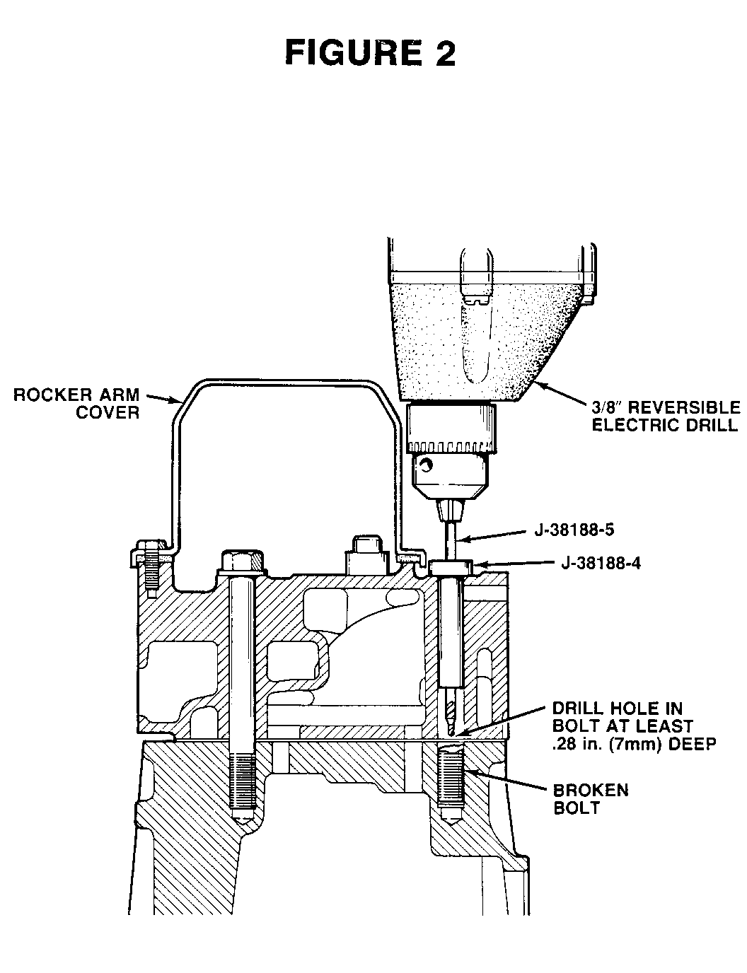
2. Insert tool J-38188-4 into the open cylinder head bolt hole.
3. Insert tool J-38188-5 into a reversible electric drill.
IMPORTANT: DO NOT USE AN AIR-POWERED DRILL - THE SPEED IS TOO FAST AND WILL CAUSE PREMATURE DRILL BIT FAILURE.
4. Referring to FIGURE 2, use J38188-5 to start a hole in the bolt.
IMPORTANT: RECOMMENDED HOLE DEPTH IS .280 in. (7 mm) MINIMUM. THE DRILL BIT MAY BE MARKED WITH A WAX PENCIL TO GAUGE THE DEPTH OF THE DRILLED HOLE. BLOW OUT DEBRIS FROM THE HOLE.
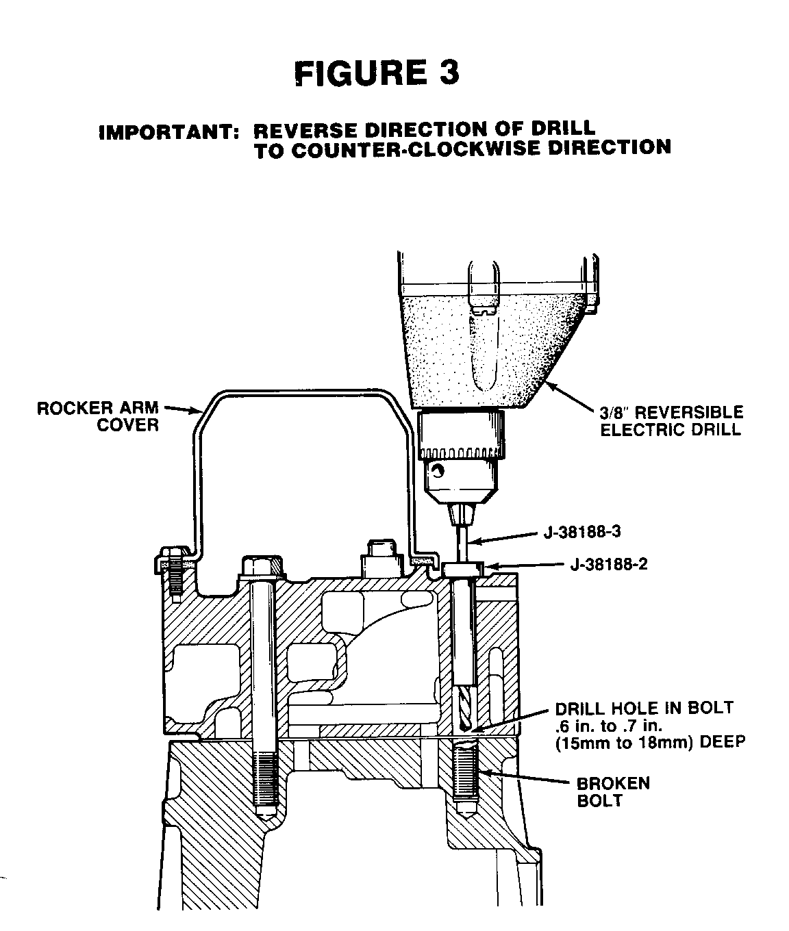
5. Replace tool J-38188-4 with tool J-38188-2.
6. Insert tool J-38188-3 into electric drill.
IMPORTANT: TOOL J-38188-3 IS A LEFT-HAND TWIST DRILL - IT IS CRITICAL THAT THE ROTATION OF THE ELECTRIC DRILL BE REVERSED PRIOR TO USING THE DRILL. ROTATION OF THE DRILL SHOULD BE COUNTER-CLOCKWISE.
7. Drill into the bolt approximately .60-.70 in. (15-17 mm) deep, see FIGURE 3. The drill may be marked in a similar manner as above for gauging hole depth.
IMPORTANT: USE CUTTING OIL AS NECESSARY DURING DRILLING.
8. Remove tool J-38188-2 from the cylinder head.
9. Using a slender rod or screwdriver and a hammer, apply a sharp impact to the bolt to help jar it loose. Blow debris from the hole.
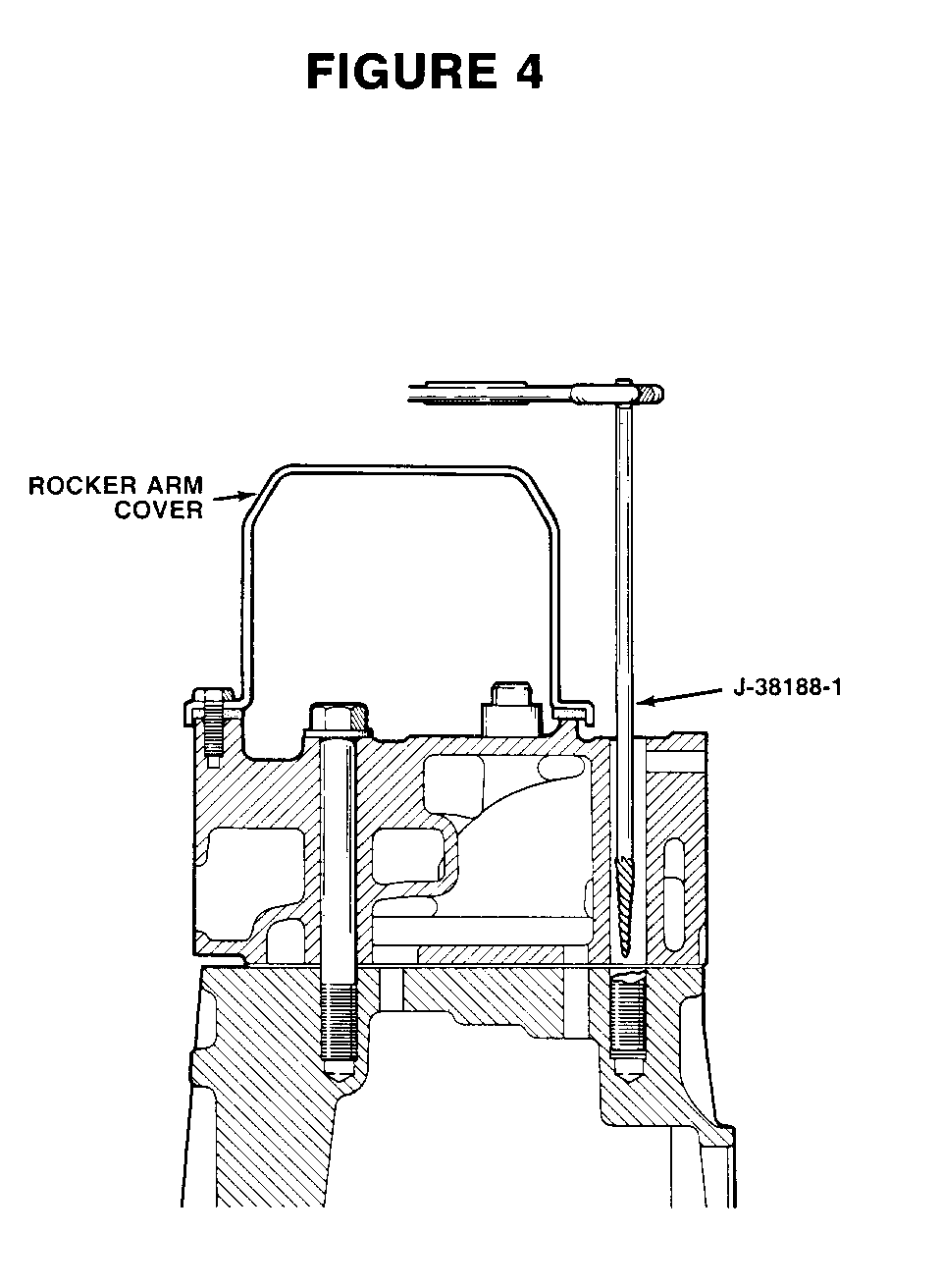
10. Using tool J-38188-1, carefully extract the bolt from the block, as shown in Fig. 4.
IMPORTANT: BLOW DEBRIS OUT OF BOLT HOLE FOLLOWING BOLT EXTRACTION.
11. Install a new bolt as selected from the "Application Table".
IMPORTANT: APPLY ENGINE OIL (e.g. 5W-30) TO BOLTS BEFORE INSTALLATION.
12. Using tool J-36660, torque the bolt to 30 N-m (22 ft/lbs), then rotate the bolt 60 degrees.
If you do not have tool J36660 use the following procedure.
A. Torque the bolts to 30 nm (22 ft. lbs.) with a standard torque wrench.
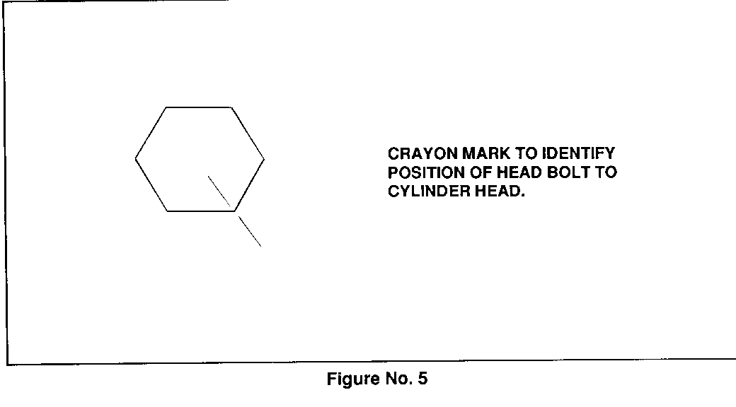
B. Using a marking crayon, place a line on head of the bolt at one of the six points and also on the cylinder head at the same location, see figure #5.
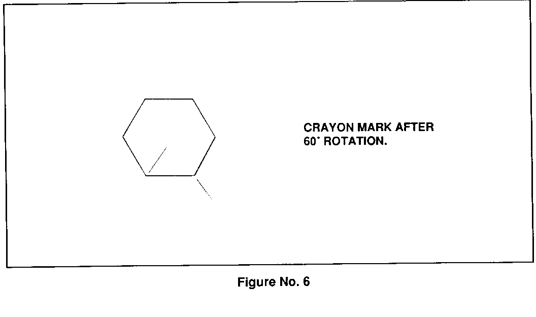
C. Continue tightening the bolt until the next point on the bolt lines up with the mark on the cylinder head, see figure #6.
13. Replace the remaining two unbroken bolts (of bolts #2, #3, or #6) with new ones as selected from the "Application Table".
NOTICE: CYLINDER HEAD BOLTS SHOULD BE REPLACED ONE A TIME. REMOVAL OF MORE THAN ONE HEAD BOLT AT A TIME CAN CAUSE UNWANTED INTERNAL AND/OR EXTERNAL COOLANT LOSS. INTERNAL COOLANT LOSS CAN CONTAMINATE OIL.
14. Repeat Step 12 when fastening the bolts.
15. If any other head bolt is broken or needs to be replaced, a new bolt should be installed as selected from the "Application Table".
16. Following head bolt replacement, the coolant system should be pressure tested per the Service Manual - Section 6B.
17. If no leakage is evident, the condition has been corrected.
18. If leakage is evident, the cylinder head gasket must be replaced. Install the appropriate gasket as shown below:
Head Gasket VIN Engine Code Part Number --------------- ----------- U 10101783 R,E,2 10101784
19. Reinstall cylinder head and replace all head bolts with new ones per the "Application Table".
20. Refer to the Service Manual - Section 6A1 for the fastening procedure and torque specifications when replacement of all head bolts is necessary.
A P P L I C A T I 0 N T A B L E
VEHICLE HEAD BOLT NEW BOLT LINE MODEL YEAR POSITION PART NUMBER ---- ---------- -------- -----------
X 1985 1-8 10044566 X 1985 9 10044568 X 1985 10 10044570
F 1985-86 1-8 10044566 F 1985-86 9 10044568 F 1985-86 10 10044570
A,P,S,T,M 1985-87 1-8 10044566 A,P,S,T,M 1985-87 9 10044568 A,P,S,T,M 1985-87 10 10044570
N 1985-87 1-8 10044565 N 1985-87 9 10044567 N 1985-87 10 10044569
IMPORTANT: APPLY ENGINE OIL (e.g. 5W-30) TO BOLTS BEFORE INSTALLATION.
General Motors bulletins are intended for use by professional technicians, not a "do-it-yourselfer". They are written to inform those technicians of conditions that may occur on some vehicles, or to provide information that could assist in the proper service of a vehicle. Properly trained technicians have the equipment, tools, safety instructions and know-how to do a job properly and safely. If a condition is described, do not assume that the bulletin applies to your vehicle, or that your vehicle will have that condition. See a General Motors dealer servicing your brand of General Motors vehicle for information on whether your vehicle may benefit from the information.
