REVISED INFO. FOR DIAGNOSIS OF STEERING WHEEL CONTROLS

Models Affected: 1989 6000
SERVICE MANUAL UPDATE
Substitute revised pages 8A-150-3, 14 through 20 for those pages originally published in your 1989 Pontiac 6000/STE Service Manual.
RADIO
G: NONE OF THE STEERING WHEEL CONTROLS OPERATE
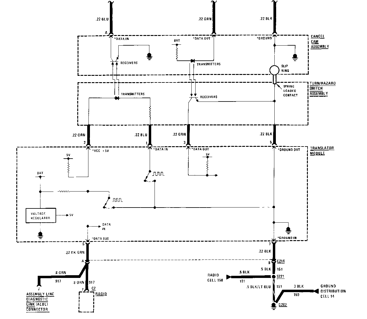
(May be caused by faulty Translator Module. Turn/Hazard Switch, Cancel Cam Assembly Switch and Electronics Module, or an open circuit.)
Inspect the ALDL connector
Is there a terminal (metal) in cavity J? | |-------------------------------------------------| YES NO | | Connect bi-directional Scan Connect the J37608 Horn Tower Test Tool at ALDL connector Adapter at the Translator Module | (see p. 150-20) | Ignition Switch in ACCY or RUN | Perform component identification using scan tool | Does scan tool show Radio is Present? | |---------------------------------------------------| NO YES | | Check ORN and DK GRN (917) wire for Does scan tool show that Steering an open between Radio and Scan Tool Wheel Controls are present? | Is this wire OK? | | | |------------------| |_------------------| | | | | NO YES YES NO | | | | Repair wire as Send Radio to an Replace the Switch Follow necessary. authorized AC and Electronics instructions Delco repair Module given on station. next page
G: NONE OF THE STEERING WHEEL CONTROLS OPERATE
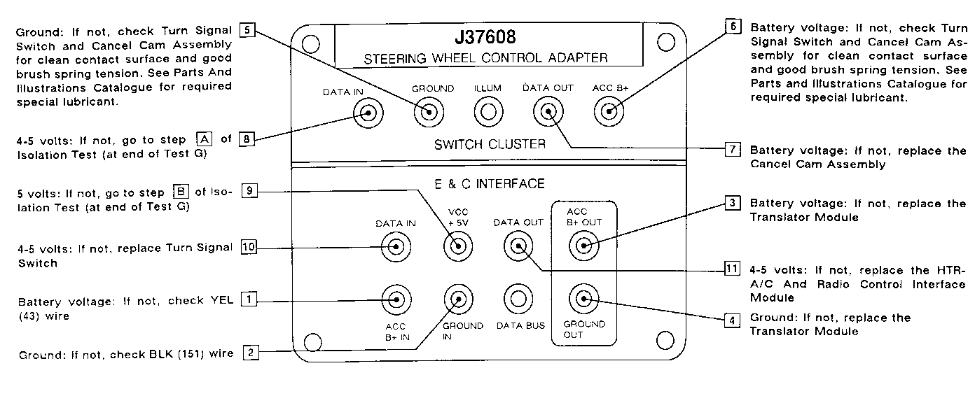
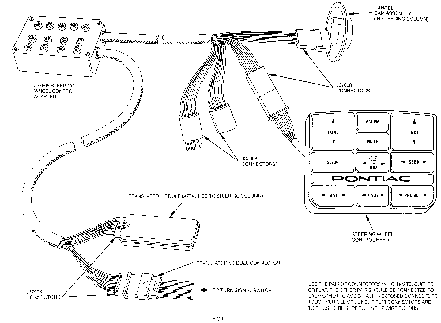
J37608 Steering Wheel Control Adapter connected (see FIG 1 on page 150-20)
Ignition Switch in RUN
Measure voltage at terminal probe cavities in numerical order (1,2,3,etc.)
J37608 probe terminals agree with schematic labels. For example, "DATA IN" on the Switch Cluster side of J37608 is the same as "DATA IN" on the cancel cam assembly on the schematic.
Test Explanation: Steps 1,2,5 and 6 verify that corresponding power of ground circuits are OK
Steps 3 and 4 verify power or ground circuits inthe Translator Moudle
Step 7 verifies Cancel Cam Assembly Internal continuity by checking for voltage.
Step 8 verifies Switch And Electronics Module "DATA IN" continuity
Step 9 verifies Translator Module Voltage regulation circuit
Step 10 verifies Turn Signal Switch transmitter internal continuity by checking for voltage
Step 11 verifies Translator Module "DATA IN" circuit continuity
G: NONE OF THE STEERING WHEEL CONTROLS OPERATE
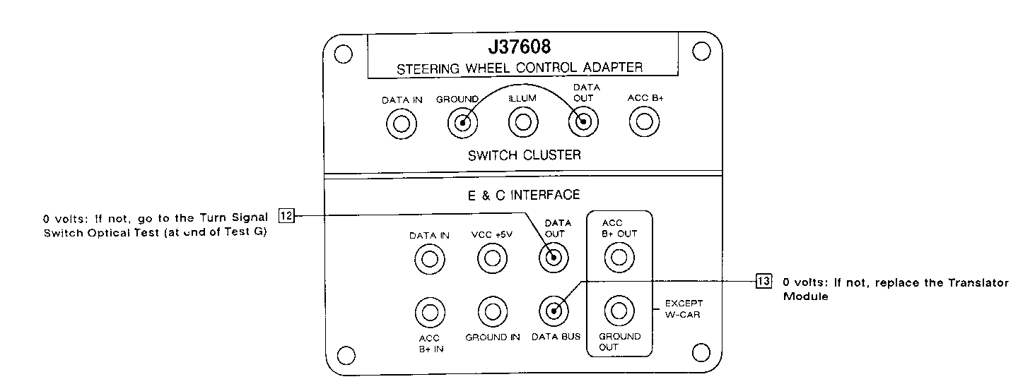
Jumper J37608 Switch Cluster terminals "DATA OUT" and "GROUND" as shown
Measure in numerical order
Test Explanation: The jumper simulates a ground signal from the Switch And Electronics Module. If the Cancel Cam Assembly transmitters and Turn Signal Switch receivers are operating, a ground signal will be transmitted through the optical slip ring and will be measured at the J37608 E & C interface probe cavity "DATA OUT". If the Translator Module is OK, the ground signal will be sent through the Translator Module and will appear at the J37608 E & C Interface 'DATA BUS" cavity.
C: NONE OF THE STEERING WHEEL CONTROLS OPERATE
Disconnect jumper from the previous step
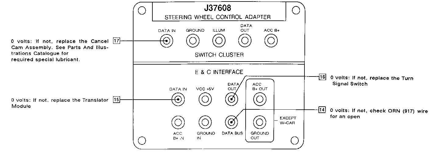
Jumper ALDL terminal J (ORN) to ground
If there is no terminal J, check the ORN (917) wire for an open, skip step 14, connect a jumper between "DATA BUS" and ground and continue with 15
Measure in numerical order
If all checks are OK, replace the Switch And Electronics Module
Test Explanation: The jumper at ALDL terminal J simulates a data signal from the Radio. If the ORN (917) wire is OK, a ground signal will appear at the J37608 "DATA BUS" terminal. If the Translator Module is OK, a ground signal will appear at the J37608 E & C interface " DATA IN' cavity. If the Turn Signal Switch transmitters are operating, the ground signal will appear at the E & C interface "DATA OUT" cav- ity. If the Cancel Cam Assembly receivers are OK, the ground signal will appear at the Switch Cluster " DATA IN" cavity. If all signals are good, Switch And Electronics Module must be at fault.
C: NONE OF THE STEERING WHEEL CONTROLS OPERATE
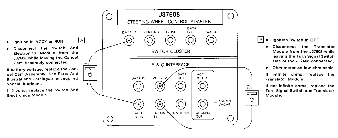
Perform only the step reterenced
Test Explanations: Step A is checking for a short to ground in the Cancel Cam Assembly. If battery voltage appears, the Cancel Cam is shorted to ground. If zero volts are measured, the Steering Wheel Controls are either shorted to ground or open. Step B is checking for a short to ground in the Turn Signal Switch. If resistance measurement is not infinite, the Turn Signal Switch is shorted and the Translator Module is also defective. If resistance is infinite, the Translator Module 5 volt regulated supply is not operating.
C: NONE OF THE STEERING WHEEL CONTROLS OPERATE
TURN SIGNAL SWITCH OPTICAL TEST
Remove the Cancel Cam Assembly
Ignition Switch in ACCY or RUN
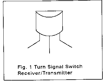
Cover one of the Turn Signal Switch Receiver/Transmitters with black electrical tape
Aim an incandescent light at the Turn Signal Switch Light Receiver/Transmitter (a flashlight will do)
Measure voltage at ALDL Connector terminal J (ORN) or at "DATA BUS" terminal of J37608
Is the measurement approximately 1 volt or less? | |--------------------------------------------| | | YES NO | | | | | | Repeat the above instructions with the Replace the Turn opposite Turn Signal Switch Receiver/ Signal Switch Transmitter covered
Is the measurement approximately 1 volt or less? |---------------------------------------------| | | YES NO | | | | | | | | Replace the Cancel Cam Assembly. See Replace the Turn Parts And illustrations Catalogue for re- Signal Switch quired special lubricant.
General Motors bulletins are intended for use by professional technicians, not a "do-it-yourselfer". They are written to inform those technicians of conditions that may occur on some vehicles, or to provide information that could assist in the proper service of a vehicle. Properly trained technicians have the equipment, tools, safety instructions and know-how to do a job properly and safely. If a condition is described, do not assume that the bulletin applies to your vehicle, or that your vehicle will have that condition. See a General Motors dealer servicing your brand of General Motors vehicle for information on whether your vehicle may benefit from the information.
