LATE TRANSAXLE UPSHIFTS RE-ADJUST T.V. CABLE

Subject: LATE TRANSAXLE UP-SHIFTS (READJUSTMENT OF T.V. CABLE)
Models Affected: 1990-1991 6000 AND GRAND PRIX MODELS WITH 4T60 TRANSMISSION
THIS BULLETIN HAS BEEN REVISED TO CHANGE THE "SHIM DIMENSION" ARTWORK AND TO CHANGE STEP 3B AND THE PARAGRAPH BELOW IT TO 2 CLICKS NOT 3 IN THE ALTERNATE CORRECTION PROCEDURE.
CONDITION:
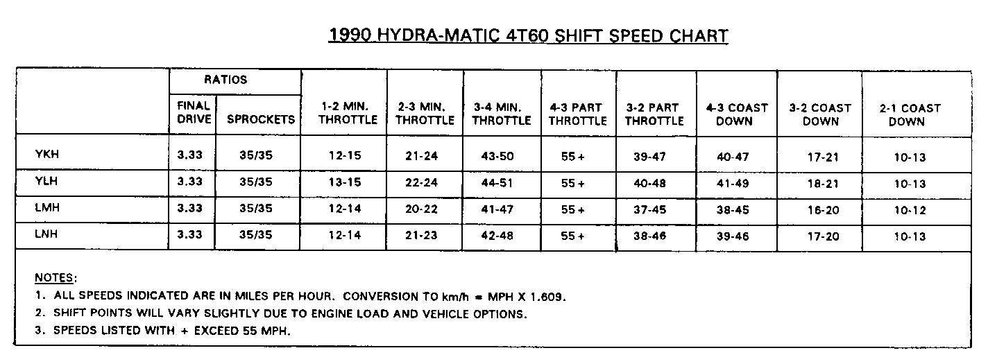
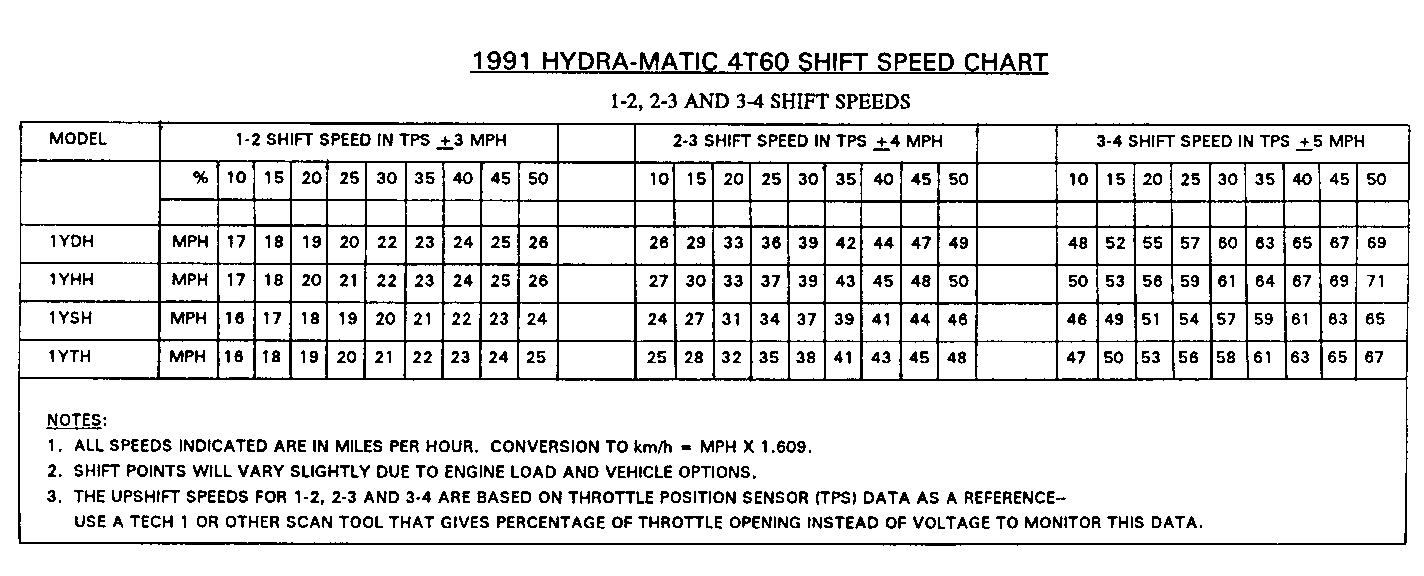
----------- Owners of the above vehicles may comment about late up-shifts for the above transaxle. Refer to the "Shift Speed Chart" to verify that the above condition does exist.
CORRECTION:
----------- The late up-shift condition may be corrected by re-setting the T.V. cable in the following method:
1. Verify that the T.V. and throttle cables are properly installed in the throttle lever and that the T.V. cable slider is in the full non-adjusted position.
If the T.V. cable assembly is NOT in the full non-adjusted position, perform step "2". otherwise, go to step "3".
2. To move the T.V. cable to the full non-adjusted position:
a. Depress and hold the adjustment button. b. Pull cable conduit out (towards the transaxle) until slider hits against adjustment stop. c. Release button.
The T.V. cable is now in the full non-adjusted position.
3. To set the T.V. cable, perform the following:
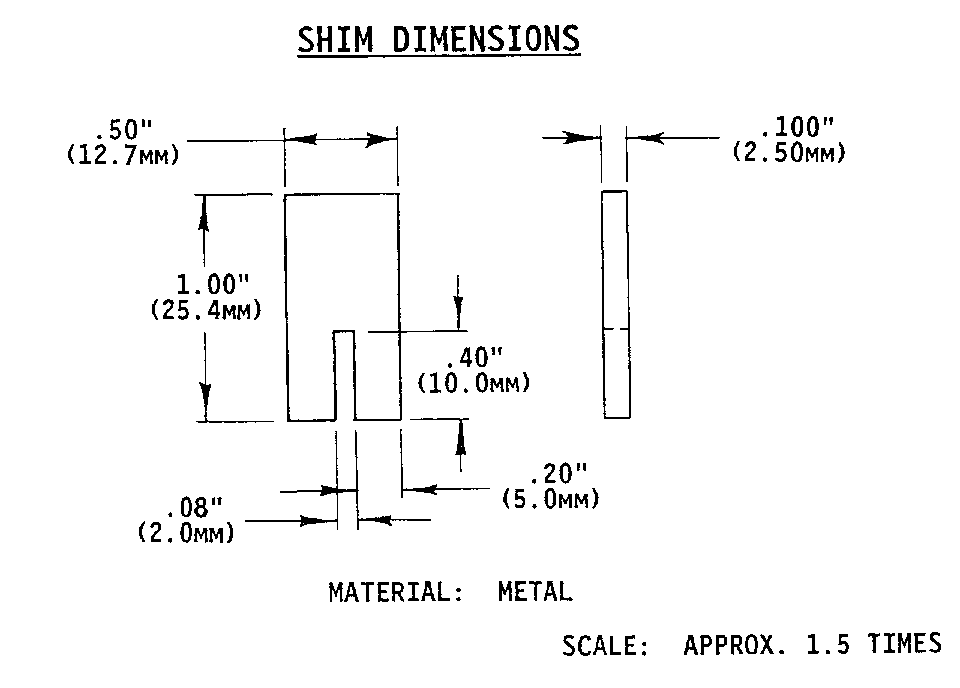
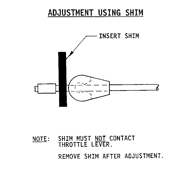
Insert shim between the plastic "Banjo" cable terminal and the cable end crimp (see figures).
Note: shim must not contact throttle lever.
b. Rotate the throttle lever to full travel position, applying no more torque than required to reach the throttle stop body. c. Remove shim.
IMPORTANT: Anytime service is performed to the T.V. system or that the T. V. cable bracket is moved, verify that the late up-shift condition does not exist as indicated by the "Shift Speed Chart". If condition exists, perform steps "1" through "3" listed above.
Use applicable labor code and time.
ALTERNATE CORRECTION PROCEDURE
Refer to the attached "Shift Speed Chart" to verify that the above condition does exist.
CORRECTION:
The late up-shift condition may be corrected by re-setting the T.V. cable in the following method:
1. Verify that the T.V. and throttle cables are properly installed in the throttle lever and that the T.V. cable slider is in the full non-adjusted position.
If the T.V. cable assembly is NOT in the full non-adjusted position, perform step "2". Otherwise, go to step "3".
2. To move the T.V. cable to the full non-adjusted position:
a. Depress and hold the adjustment button. (Temporary removal of the valve block located above the adjustment button may provide additional working clearance.) b. Pull cable conduit out (towards the transaxle) until slider hits against adjustment stop. c. Release button. d. Re-install the valve block if removed.
The T.V. cable is now in the full non-adjusted position.
3. To set the T.V. cable, perform the following:
a. Rotate the throttle lever to full travel position, applying no more torque than required to reach the throttle stop body. b. While holding the throttle lever in the full travel position, pull up on the T.V. cable to obtain two (2) additional clicks.
If it is not possible to obtain the two (2) additional clicks described above, perform the following procedures:
4. Loosen the T.V. cable bracket nuts (2) located at the Intake plenum. 5. Move the bracket towards the throttle lever as far as it will go. 6. Tighten the bracket nuts (2) to 10 N.m (8 lbs. ft.). 7. Repeat steps 1 through 3 stated above.
Test drive the vehicle to verify the condition is eliminated.
NOTE: Anytime service is performed to the T.V. system or that the T.V. cable bracket is moved, verify that the late up-shift condition does not exist as indicated by the "Shift Speed Chart". If condition exists, perform steps "1" through "3" listed above.
Use applicable labor code and time. (K5245, .4)


General Motors bulletins are intended for use by professional technicians, not a "do-it-yourselfer". They are written to inform those technicians of conditions that may occur on some vehicles, or to provide information that could assist in the proper service of a vehicle. Properly trained technicians have the equipment, tools, safety instructions and know-how to do a job properly and safely. If a condition is described, do not assume that the bulletin applies to your vehicle, or that your vehicle will have that condition. See a General Motors dealer servicing your brand of General Motors vehicle for information on whether your vehicle may benefit from the information.
