Circuit Description
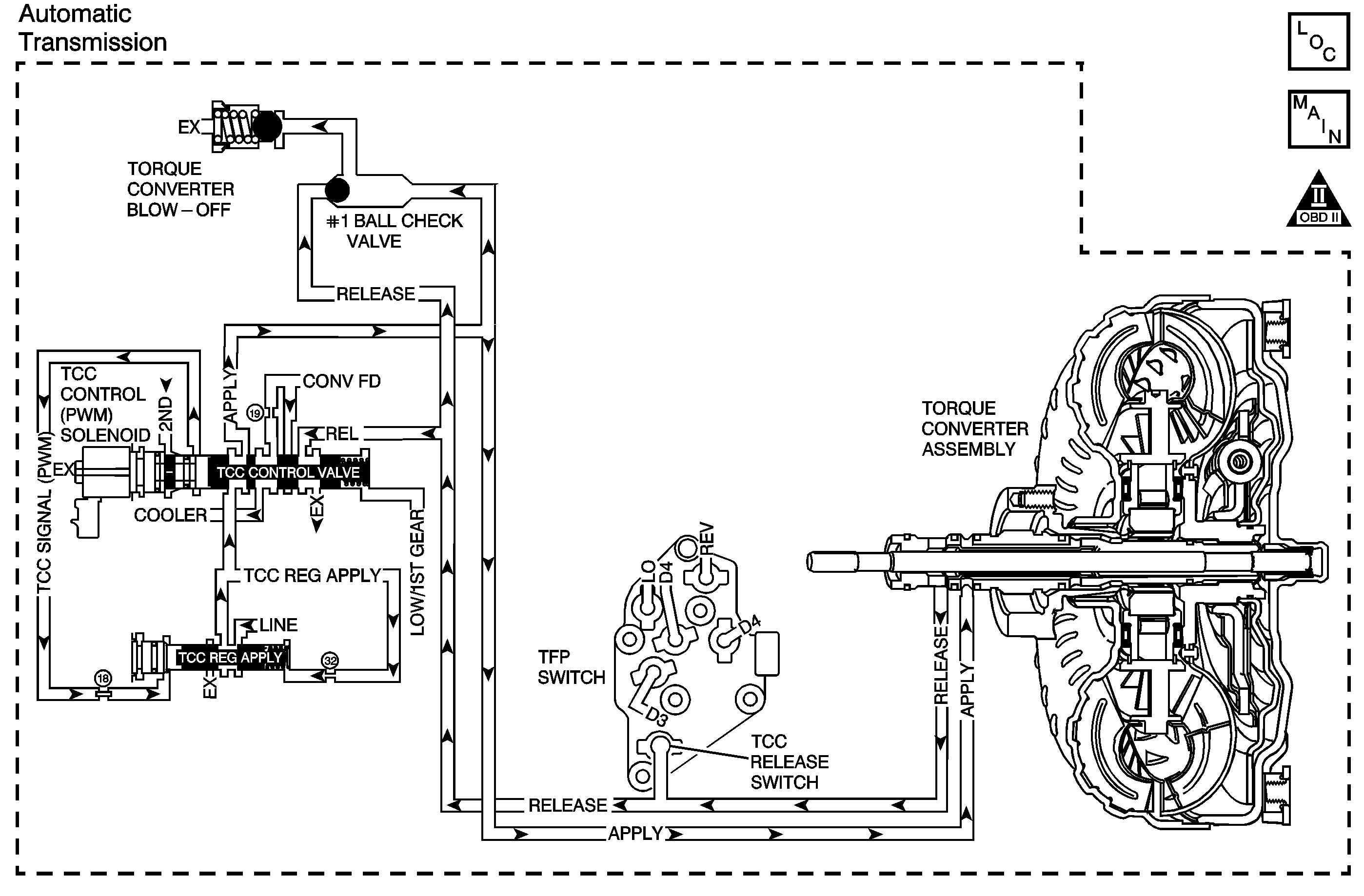
The PCM controls the torque converter clutch pulse width modulation (TCC PWM) solenoid valve. The solenoid controls the hydraulic fluid for TCC apply and release. When the TCC is fully applied, the engine is coupled directly to the transmission through the TCC.
The TCC used is an electronically controlled capacity clutch (ECCC). The PCM will normally allow a small amount of slip to occur with the ECCC. When the TCC is engaged, TCC slip speed is maintained at approximately 20 to 50 RPM.
If the PCM detects high torque converter slip when the TCC is commanded ON, then DTC P0741 sets. DTC P0741 is a type B DTC.
Conditions for Running the DTC
| • | No TP sensor DTC P0121, P0122 or P0123. |
| • | No VSS DTC P0502 or P0503. |
| • | No AT ISS sensor DTC P0716 or P0717. |
| • | No TCC stuck ON DTC P0742. |
| • | No Shift Solenoid DTCs P0751, P0752, P0753, P0756, P0757, or P0758. |
| • | No TFP manual valve position switch DTC P1810. |
| • | No TCC PWM solenoid valve DTC P1860. |
| • | No TCC release switch DTC P1887. |
| • | The engine speed is greater than 500 RPM for 5 seconds and not in fuel shut off. |
| • | The transmission gear range is D4, D3 or D2. |
| • | The time since the last gear range change is greater than 6 seconds. |
| • | The transmission fluid temperature is 20-130°C (68-266°F). |
| • | The TP angle is 4-35%. |
| • | The TCC PWM solenoid valve is commanded ON for more than 0.5 seconds. |
Conditions for Setting the DTC
The following conditions exist for two times during one ignition cycle.
| • | The TCC duty cycle is greater than 50 percent. |
| • | The TCC slip speed is greater than 180 RPM for 7 seconds. |
Action Taken When the DTC Sets
| • | The PCM illuminates the malfunction indicator lamp (MIL) during the second consecutive trip in which the Conditions for Setting the DTC are met. |
| • | The PCM inhibits TCC. |
| • | The PCM inhibits 4th gear if the transmission is in Hot Mode. |
| • | The PCM freezes shift adapts. |
| • | The PCM records the operating conditions when the Conditions for Setting the DTC are met. The PCM stores this information as Freeze Frame and Failure Records. |
| • | The PCM stores DTC P0741 in PCM history during the second consecutive trip in which the Conditions for Setting the DTC are met. |
Conditions for Clearing the MIL/DTC
| • | The PCM turns OFF the MIL during the third consecutive trip in which the diagnostic test runs and passes. |
| • | A scan tool can clear the MIL/DTC. |
| • | The PCM clears the DTC from PCM history if the vehicle completes 40 warm-up cycles without an emission-related diagnostic fault occurring. |
| • | The PCM cancels the DTC default actions when the ignition switch is OFF long enough in order to power down the PCM. |
Test Description
The numbers below refer to the step numbers on the diagnostic table.
Step | Action | Value(s) | Yes | No | ||||||||||||||||
|---|---|---|---|---|---|---|---|---|---|---|---|---|---|---|---|---|---|---|---|---|
1 | Did you perform the Powertrain Diagnostic System Check? | -- | Go to Step 2 | Go to Diagnostic System Check - Engine Controls in Engine Controls | ||||||||||||||||
2 | Did you perform the transmission fluid checking procedure? | -- | Go to Step 3 | Go to Transmission Fluid Check | ||||||||||||||||
3 |
Important: Before clearing the DTCs, use the Scan Tool in order to record the Freeze Frame and Failure Records for reference. Using the Clear Info function will erase the stored Freeze Frame and Failure Records from the PCM. Does the Scan Tool indicate Yes for TCC Release Pressure? | -- | Go to Step 5 | Go to Step 4 | ||||||||||||||||
4 |
Refer to Transmission Overhaul in the 4T65-E Section of the Transmission Unit Repair Manual. Did you complete the repair? | -- | Go to Step 7 | -- | ||||||||||||||||
Does the Scan Tool indicate the slip speed is within the specified value? | -50 RPM to +50 RPM | Go to Intermittent Conditions in Engine Controls | Go to Step 6 | |||||||||||||||||
6 |
Refer to Transmission Overhaul in the 4T65-E Section of the Transmission Unit Repair Manual. Did you complete the repair? | -- | Go to Step 7 | -- | ||||||||||||||||
7 | Perform the following procedure in order to verify the repair:
Has the test run and passed? | -- | System OK | Go to Step 1 |
