For 1990-2009 cars only
Removal Procedure
- Disconnect the battery negative cable. Refer to Battery Negative Cable Disconnection and Connection in Engine Electrical.
- Disable the SIR system. Refer to SIR Disabling and Enabling or SIR Disabling and Enabling in SIR.
- Remove the covers from the right and the left access holes on the instrument panel (I/P). Refer to Instrument Panel Outer Trim Cover Replacement .
- Remove the I/P insulators. Refer to Instrument Panel Insulator Panel Replacement - Right Side and Instrument Panel Insulator Panel Replacement - Left Side .
- Remove the data link connector (DLC). Refer to Data Link Connector Replacement in Computer/Integrating Systems.
- Remove the side upper garnish moldings from the windshield. Refer to Windshield Pillar Garnish Molding Replacement in Interior Trim.
- Remove the upper trim pad from the I/P. Refer to Instrument Panel Upper Trim Pad Replacement .
- Remove the front floor console. Refer to Front Floor Console Replacement .
- Remove the knee bolster panel. Refer to Knee Bolster Replacement .
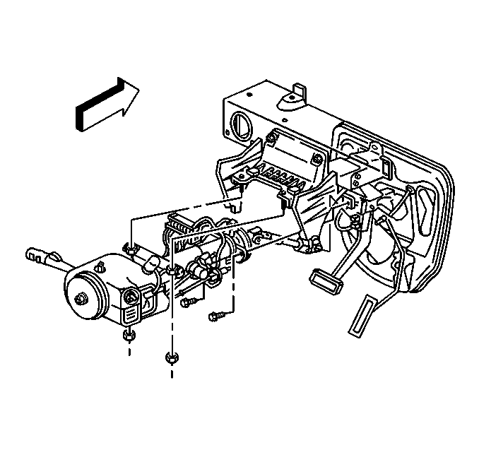
- Remove the bolts from the lower steering column.
- Remove the nuts from the upper steering column.
- Lower the steering column.
- Remove the hood release handle. Refer to Hood Primary Latch Release Cable Handle Replacement in Body Front End.
- Remove the accessory trim plate from the I/P. Refer to Instrument Panel Accessory Trim Plate Replacement .
- Remove the instrument panel cluster (IPC) trim plate bezel. Refer to Instrument Panel Cluster Trim Plate Bezel Replacement .
- Remove the IPC. Refer to Instrument Cluster Replacement .
- Remove the radio. Refer to Radio Replacement in Entertainment.
- Remove the heater A/C control. Refer to HVAC Control Module Replacement in HVAC Systems - Manual.
- Remove the I/P compartment. Refer to Instrument Panel Compartment Replacement .
- Remove the I/P compartment lamp switch. Refer to Instrument Panel Compartment Lamp Switch Replacement Lighting Systems.
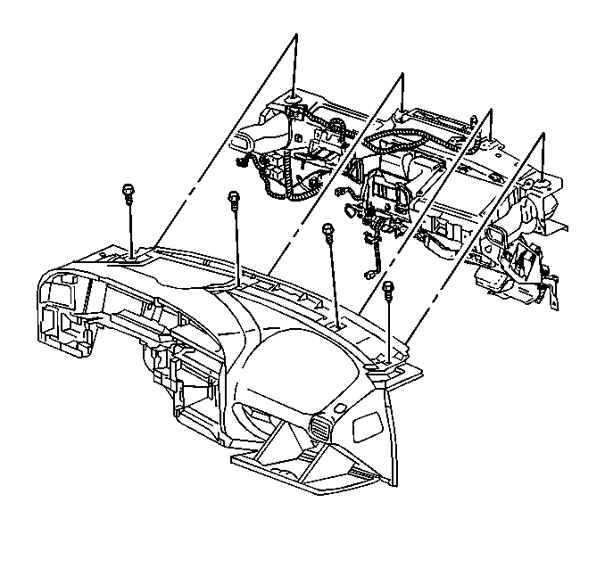
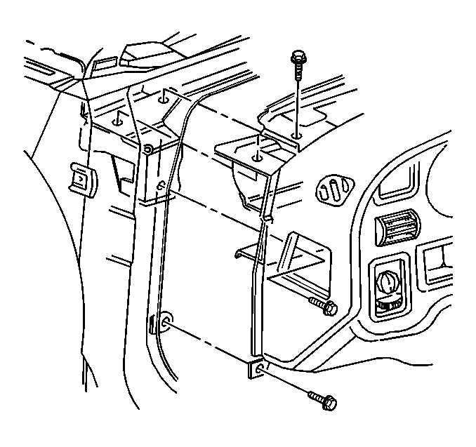
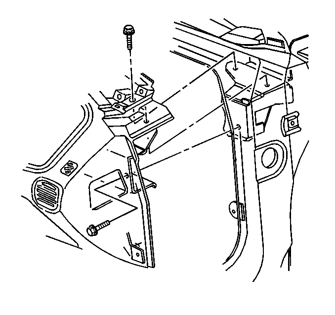
- Remove the I/P mounting screws.
- Reposition the I/P wiring harness.
- Remove the I/P.
Caution: Refer to SIR Caution in the Preface section.


Installation Procedure
- Align the I/P to the vehicle.
- Reposition the I/P wiring harness.
- Install the I/P mounting bolts at the cluster pocket.
- Install the I/P mounting bolts at the windshield.
- Install the I/P mounting bolts to the compartment.
- Install the I/P compartment lamp switch. Refer to Instrument Panel Compartment Lamp Switch Replacement in Lighting Systems.
- Install the I/P compartment. Refer to Instrument Panel Compartment Replacement .
- Install the IPC. Refer to Instrument Cluster Replacement .
- Install the heater A/C control. Refer to HVAC Control Module Replacement in HVAC Systems - Manual.
- Install the radio. Refer to Radio Replacement in Entertainment.
- Install the IPC trim plate bezel. Refer to Instrument Panel Cluster Trim Plate Bezel Replacement .
- Install the I/P accessory trim plate. Refer to Instrument Panel Accessory Trim Plate Replacement .
- Install the hood release handle. Refer to Hood Primary Latch Release Cable Handle Replacement in Body Front End.
- Raise the steering column.
- Install the nuts to the upper steering column.
- Install the bolts to the lower steering column.
- Install the knee bolster panel. Refer to Knee Bolster Replacement .
- Install the front floor console. Refer to Front Floor Console Replacement .
- Install the I/P upper trim panel. Refer to Instrument Panel Upper Trim Pad Replacement .
- Install the windshield side upper garnish moldings. Refer to Windshield Pillar Garnish Molding Replacement in Interior Trim.
- Install the I/P insulators. Refer to Instrument Panel Insulator Panel Replacement - Right Side and Instrument Panel Insulator Panel Replacement - Left Side .
- Install the DLC. Refer to Data Link Connector Replacement in Computer/Integrating Systems.
- Install the I/P access hole covers. Refer to Instrument Panel Outer Trim Cover Replacement .
- Enable the SIR system. Refer to SIR Disabling and Enabling or SIR Disabling and Enabling in SIR.
- Connect the battery negative cable. Refer to Battery Negative Cable Disconnection and Connection in Engine Electrical.

Notice: Refer to Fastener Notice in the Preface section.
Tighten
Tighten the mounting bolts to 5 N·m
(44 lb in).

Tighten
Tighten the mounting bolts to 5 N·m
(44 lb in).

Tighten
Tighten the mounting bolts to 2 N·m
(18 lb in).

Tighten
Tighten the nuts to 25 N·m (18 lb ft).
Tighten
Tighten the bolts to 25 N·m (18 lb ft).
