Removal Procedure
- Remove the instrument panel (IP) trim pad. Refer to Instrument Panel Trim Pad Replacement .
- Remove the brake pedal bracket and the reinforcement. Refer to Brake Pedal Assembly Replacement .
- Reroute the transmission shift cable through the cross vehicle beam. Refer to Range Selector Lever Cable Adjustment in Automatic Transmission.
- Release the retaining clips from the IP wiring harness and reposition the wiring harness out of the way.
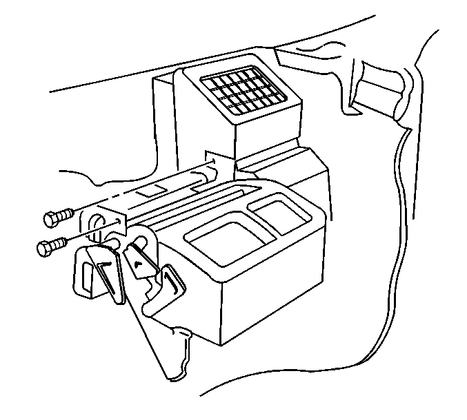
- Remove the bolts retaining the HVAC module to the cross vehicle beam.
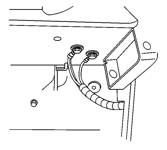
- Remove the left cross vehicle ground wire.
- Remove the right cross vehicle ground wires.
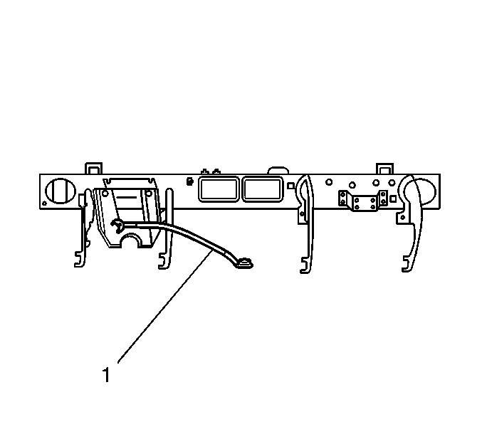
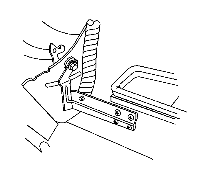
- Unbolt the cross vehicle anchor tether (1) and let the tether hang.
- Unclip the antenna cable from the cross vehicle beam.
- Remove the HVAC bracket from the cross vehicle beam bracket.
- Remove the heads up display (HUD) bracket, if equipped. Refer to Head Up Display Module Replacement .
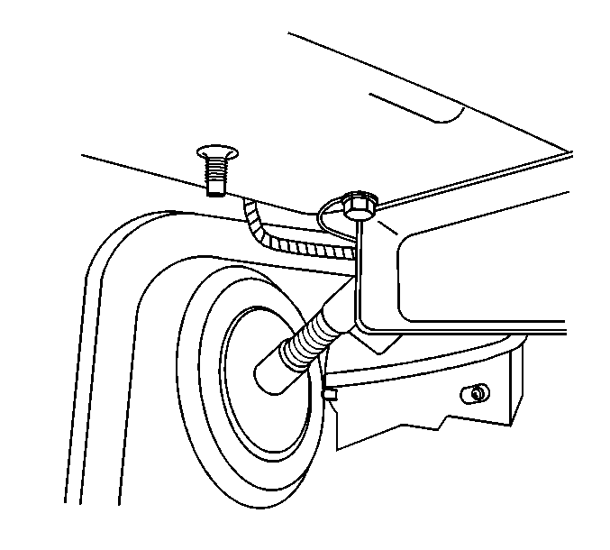
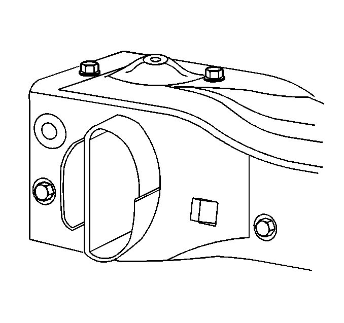
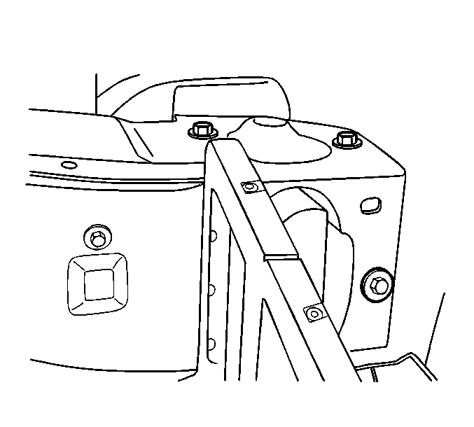
- Remove the bolts retaining the cross vehicle beam to the left hinge pillar.
- Remove the bolts retaining the cross vehicle beam to the right hinge pillar.
- If you cannot remove the inner bolt because of interference with the windshield, gently bend the bolt stem when you remove the bolt from the cross vehicle beam. DISCARD the bolt.
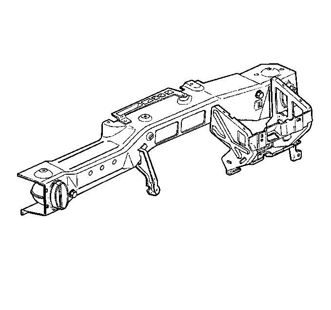
- Remove the cross vehicle beam from the vehicle through the main wire harness.
- Remove the front defroster duct.
Caution: This vehicle is equipped with a Supplemental Inflatable Restraint (SIR) System. Failure to follow the correct procedure could cause the following conditions:
• Air bag deployment • Personal injury • Unnecessary SIR system repairs • Refer to SIR Component Views in order to determine if you are performing service on or near the SIR components or the SIR wiring. • If you are performing service on or near the SIR components or the SIR wiring, disable the SIR system. Refer to Disabling the SIR System.
Installation Procedure
- Install the front defroster duct.
- Install the cross vehicle beam to the vehicle through the main wire harness.
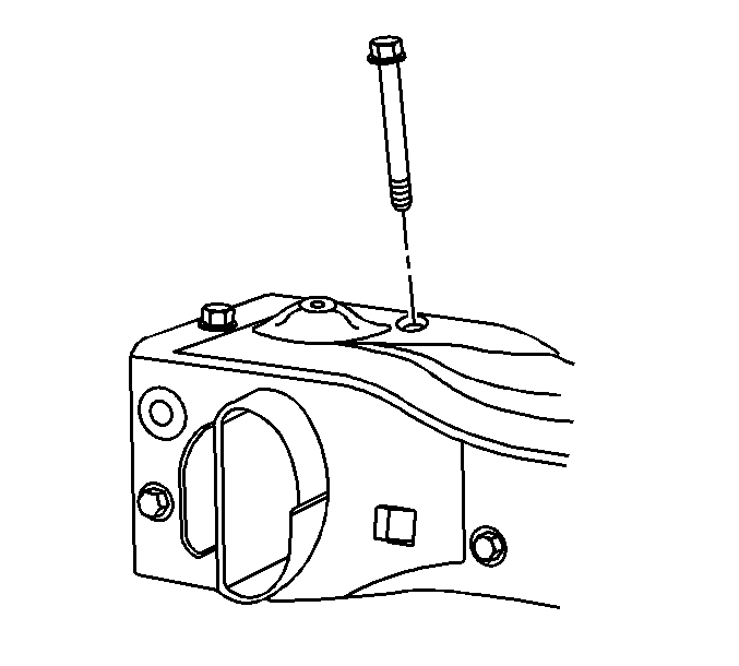
- If you had to bend the cross vehicle beam bolt during removal, perform the following procedure:
- Loosely install the bolts which secure the cross vehicle beam to the right hinge pillar.
- Loosely install the bolts which secure the cross vehicle beam to the left hinge pillar.
- Tighten all the bolts which secure the cross vehicle beam to the pillars.
- Install the HVAC module to the cross vehicle beam with the retaining bolts.
- Install the bolts which retain the HVAC module to the center support bracket.
- Install the IP wiring harnesses into position and secure the retaining clips.
- Install the cross vehicle anchor tether (1).
- Clip the antenna cable to the cross vehicle beam.
- Install the HVAC bracket to the cross vehicle beam bracket.
- Install the HUD bracket, if equipped. Refer to Head Up Display Module Replacement .
- Install the brake pedal bracket and the reinforcement. Refer to Brake Pedal Assembly Replacement .
- Install the IP trim pad. Refer to Instrument Panel Trim Pad Replacement .
- Install the front floor console. Refer to Front Floor Console Replacement .

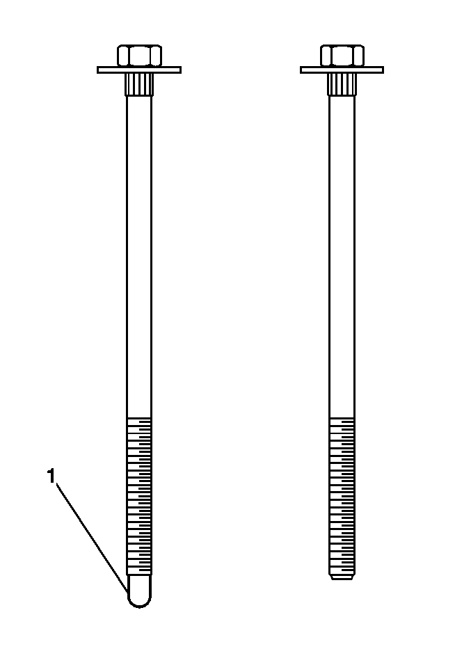
| 3.1. | Install a NEW bolt. |
| 3.2. | When reinstalling the instrument panel carrier with new bolt, You must shorten it 4-5 mm (3/16 in) by cutting off the guide feature (1) as shown. |
| 3.3. | if necessary, clean the threads prior to installation using a die. |
| 3.4. | When installed, 5-6 threads of the bolt should protrude through the fastener. |

Important: Do NOT tighten the bolts.

Notice: Use the correct fastener in the correct location. Replacement fasteners must be the correct part number for that application. Fasteners requiring replacement or fasteners requiring the use of thread locking compound or sealant are identified in the service procedure. Do not use paints, lubricants, or corrosion inhibitors on fasteners or fastener joint surfaces unless specified. These coatings affect fastener torque and joint clamping force and may damage the fastener. Use the correct tightening sequence and specifications when installing fasteners in order to avoid damage to parts and systems.
Tighten
Tighten the bolts to 25 N·m (18 lb ft).

Tighten
Tighten the bolts to 10 N·m (89 lb in).
Tighten
Tighten the bolts to 10 N·m (89 lb in).


