Tire and Wheel Rotational Speed Calculation
A size P235/75R15 tire rotates ONE complete revolution per second (RPS), or 1 Hz, at a vehicle speed of 8 km/h (5 mph). This means that at 16 km/h (10 mph), the same tire will make TWO complete revolutions in one second, 2 Hz, and so on.
Tire Size | Tread | Revs/Sec (Hertz) at 8 km/h (5 mph) |
|---|---|---|
P215/65R16 | ALS | 1.07 |
P215/70R16 | AL2 | 1.03 |
P215/70R15 | ALS | 1.07 |
Tread Code | ||
ALS | All Season | |
AL2 | Touring | |
- Determine the rotational speed of the tires in revolutions per second (RPS), or Hertz (Hz), at 8 km/h (5 mph), based on the size of the tires. Refer to the Tire Rotational Speed table.
- Determine the number of increments of 8 km/h (5 mph) that are present, based on the vehicle speed (km/h, mph) at which the disturbance occurs.
- Determine the rotational speed of the tires in revolutions per second (Hz), at the specific vehicle speed (km/h, mph) at which the disturbance occurs.
- Compare the rotational speed of the tires at the specific vehicle speed at which the disturbance occurs, to the dominant frequency recorded on the J 38792-A during testing. If the frequencies match, then a first-order disturbance related to the rotation of the tire/wheel assemblies is present.
- To compute higher order tire/wheel assembly rotation related disturbances, multiply the rotational speed of the tires at the specific vehicle speed at which the disturbance occurs, by the order number:
For example: According to the Tire Rotational Speed table, a P215/65R16 tire makes 1.07 revolutions per second (Hz) at a vehicle speed of 8 km/h (5 mph). This means that for every increment of 8 km/h (5 mph) in vehicle speed, the tire's rotation increases by 1.07 revolutions per second (Hz).
For example: Assume that a disturbance occurs at a vehicle speed of 96 km/h (60 mph). A speed of 96 km/h (60 mph) has 12 INCREMENTS of 8 km/h (5 mph):
96 km/h (60 mph) divided by 8 km/h (5 mph) = 12 increments
For example: To determine the tire rotational speed at 96 km/h (60 mph), multiply the number of increments of 8 km/h (5 mph) by the revolutions per second (Hz) for one increment:
12 (increments) X 1.07 Hz = 12.84 Hz (rounded to 13 Hz)
If the frequencies do not match, then the disturbance may be related to a higher order of tire/wheel assembly rotation.
13 Hz X 2 (for second order) = 26 Hz second-order tire/wheel assembly rotation related
13 Hz X 3 (for third order) = 39 Hz third-order tire/wheel assembly rotation related
If any of these computations match the frequency of the disturbance, a disturbance of that particular order, relating to the rotation of the tire/wheel assemblies is present.
Propeller Shaft Rotational Speed
The rear differential assembly is designed to provide on-demand drive torque to the rear tire and wheel assemblies as needed. The differential incorporates clutch packs that are fed differential gear lubricant by gerotor pumps under certain conditions to provide the needed drive torque to the rear wheels. The rear differential assembly is designed to allow varying amounts of slip between the amount of input torque coming from the transfer case through the propeller shaft, and the amount of torque being delivered to the rear tire and wheel assemblies.
The propeller shaft is rotated by the transfer case during any movement of the vehicle -- even when the all-wheel drive (AWD) system is disabled. The transfer case is attached directly to the transaxle and incorporates functions of the transaxle extension housing. The transfer case operates using the final drive ratio of the transaxle output shafts as input to the case. The transfer case then modifies the transmission output ratio very slightly for the propeller shaft by a factor of 1.013:1. As a result, the propeller shaft then rotates at approximately the same speed as the front tire and wheel assemblies.
If the (first-order) rotational speed of the tires is determined to be 13 Hz, then the (first-order) rotational speed of the propeller shaft would also be 13 Hz. The slight ratio change that occurs through the transfer case will have little affect on the propeller shaft rotational speed:
13 Hz X 1.013 transfer case (output) ratio = 13.169 Hz (still rounded to 13 Hz) first-order propeller shaft rotation related disturbance
The propeller shaft uses front and rear constant-velocity (CV) joints. Each CV joint uses a 6-ball bearing design. It would be possible to have a sixth-order propeller shaft rotational disturbance.
To compute a sixth-order propeller shaft rotation related disturbance, multiply the first order rotational speed of the propeller shaft by the order number of 6:
13 Hz X 6 (for sixth order) = 78 Hz sixth-order propeller shaft rotation related disturbance
Using the non-rounded numbers, you would derive an answer of 79 Hz for sixth-order propeller shaft rotation.
Component Rotational Speed Worksheet
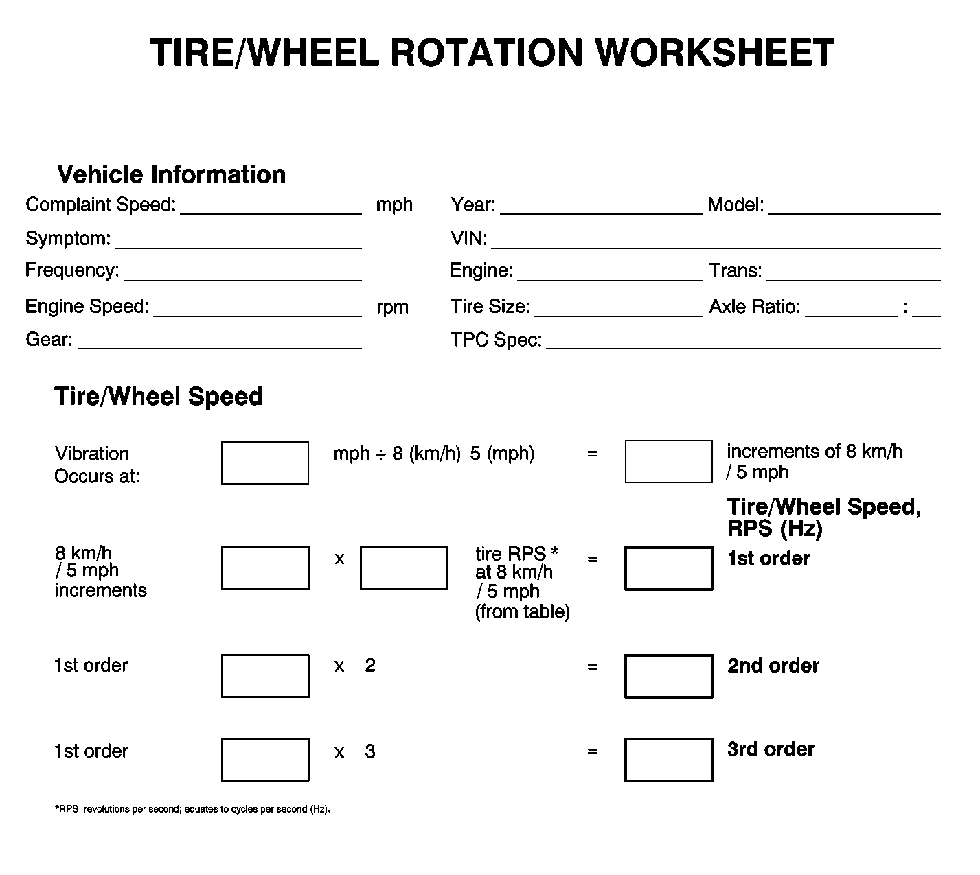
Utilize the following worksheet as an aid in calculating the first, second and third order of tire/wheel assembly rotational speed related disturbances that may be present in the vehicle.
If after completing the Tire/Wheel Rotation Worksheet, the frequencies calculated do NOT match the dominant frequency of the disturbance recorded during testing, either recheck the data, or attempt to rematch the figures allowing for 1½-8 km/h (1-5 mph) of speedometer error.
If the possible tire/wheel assembly and/or propeller shaft rotational speed related frequencies still do not match the dominant frequency of the disturbance, the disturbance is most likely torque/load sensitive.
If after completing the Tire/Wheel Rotation Worksheet, one of the frequencies calculated DOES match the dominant frequency of the disturbance, the disturbance is related to the rotation of that component group, (tire/wheel assembly or propeller shaft related).

