STEERING COLUMN REPLACEMENT REVISED PROCEDURE

VEHICLES AFFECTED: 1984-85 Caprice and Monte Carlo -------------------------------
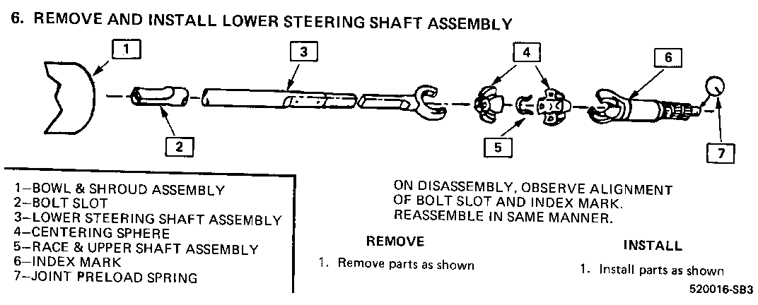
The procedures for steering column removal and installation for the above models have been revised. Please update Section 3B5 of the 1984 and 1985 Caprice and Monte Carlo Shop Manuals (ST-329-84 and ST-329-85).
COLUMN REMOVAL
Note: Install seat cover.
1. Open hood and disconnect negative battery cable.
2. Remove clamp bolt from coupling at lower end of column shaft.
3. Disconnect shift linkage from shift tube lever at lower end of steering column.
4. If column is to be replaced or repaired (out of vehicle),remove the steering wheel. Refer to 'steering wheel removal'.
5. Remove sound insulator pad.
6. Remove lower steering column cover.
7. Remove trim cap or lower trim panel from instrument panel.
8. Remove cover and toe-pan attaching screws.
9. If equipped with column shift, remove shift indicator needle from shift bowl.
10. Remove the two upper steering column to instrument panel attaching nuts, while holding column in position.
11. Lower the column and disconnect the wiring connectors.
12. Carefully remove the steering column from outside the vehicle.
COLUMN SERVICE ON BENCH
1. Remove column support bracket and wiring protector.
2. Install column holding fixutre J-23074.
3. Install column and tool into vise.
4. Remove lock plate cover.
5. Remove lock plate and retainer.
Continue Column Service As Shown In Service Manual.
INSTALLATION
See 'Fastener Notice' on page 1 of this section.
1. Carefully position steering column from inside of vehicle through toe pan.
2. Connect all wiring connectors before raising column into place.
3. Raise the column into position and loosely install the two upper steering column to instrument attaching nuts, while holding column in position.
4. Install intermediate shaft onto lower steering column shaft. Install clamp bolt and nut. Torque nut to 70 N.m (51 ft. lbs.)
5. Visually chack flex-coupling alignment. Flex coupling must be straight within 1.59 mm (1/16 in.1 without bottoming intermediate shaft coupling. If incorrect, move column aseembly to seat requirement.
6. Install and torque toe-pan screws to 6 N.m (4.5 ft. lbs.)
7. Torque the two upper column to instrument panel attaching nuts to; 20-34 N.m (14.5-25 ft. lbs.)
8. With column shifte install shift indicator needle.
9. Install trin cap and lower trim panel.
10. If steering wheel was removed, refer to steering wheel installation.
11. Connect negative battery cable to battery.

General Motors bulletins are intended for use by professional technicians, not a "do-it-yourselfer". They are written to inform those technicians of conditions that may occur on some vehicles, or to provide information that could assist in the proper service of a vehicle. Properly trained technicians have the equipment, tools, safety instructions and know-how to do a job properly and safely. If a condition is described, do not assume that the bulletin applies to your vehicle, or that your vehicle will have that condition. See a General Motors dealer servicing your brand of General Motors vehicle for information on whether your vehicle may benefit from the information.
