FRONT SEAT AUTOMATIC SAFETY BELT, INOPERABLE COMFORT LOCK

FRONT SEAT AUTOMATIC SAFETY BELT INOPERABLE COMFORT LOCK
MODELS AFFECTED: 1987 BONNEVILLE MODELS EQUIPPED WITH AUTOMATIC SAFETY BELT SYSTEM
Some early built cars with Automatic Safety Belt System may have an inoperable or intermittent comfort lock. The following procedure should be followed if this condition is noted:
INSPECT
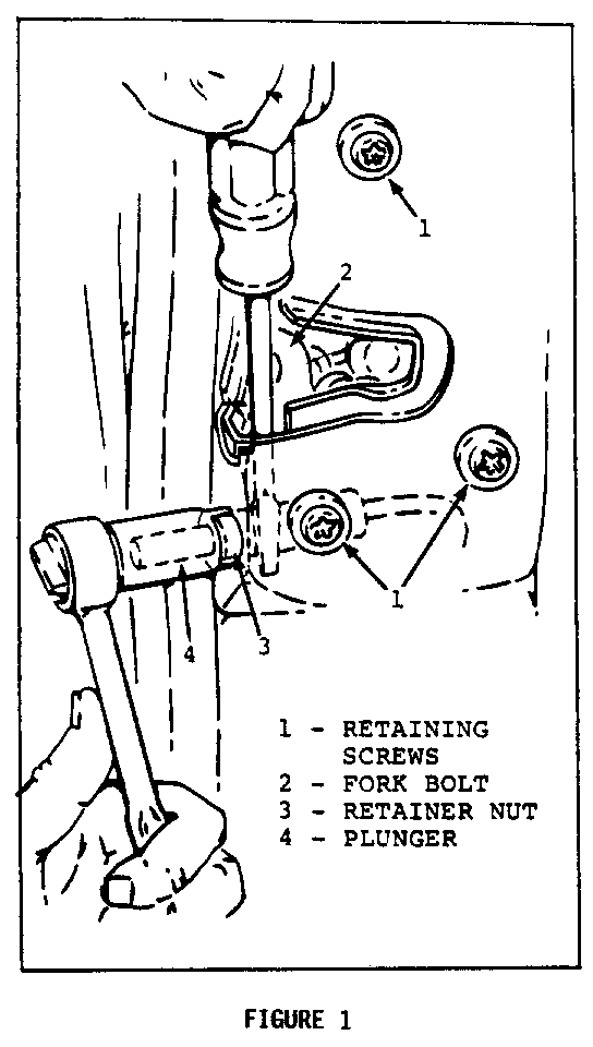
1. Inspect by depressing plunger (4) on door and note if it travels inward to a flush condition freely (see Figure 1).
2. Depress plunger (4). While depressed, pull the shoulder belt out at least 130 millimeters (5 inches) and release. Still holding plunger depressed, pull shoulder belt out a second time, about 25 millimeters (1 inch) to set comfort lock. Release plunger (4). Note if plunger returns freely and releases comfort lock; if not, replace retainer nut (3) with Part Number 20654113.
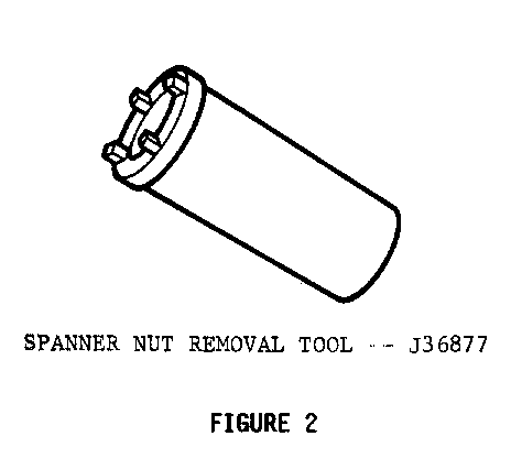
NOTICE: USE SPANNER NUT REMOVAL TOOL J-36877 (SEE FIGURE 2).
To replace plunger retaining nut, follow the procedure indicated below:
REPLACE COMFORT PLUNGER RETAINER NUT
NOTICE: DO NOT REMOVE DOOR TRIM.
1. Loosen door latch retaining screws (1); do not completely remove them (see Figure 1)
2. Rotate fork bolt (2) upward.
3. Place screwdriver between door latch and door sheet metal and apply downward pressure to prevent plunger body from turning.
4. Remove retaining nut (3) with Tool J-36877.
5. With screwdriver still in place, install new nut (3) , Part Number 20654113, and torque to 8-10 N.m (6-7 lb. ft.).
6. Tighten door latch retaining screws (1) to 6-7.5 N.m (4.5-5.5 lb. ft.).
7. Rotate fork bolt (2) downward.
8. Inspect operation by repeating Steps 1 and 2 of inspection procedure. If plunger does not return and comfort lock does not release; continue to plunger and cable assembly replacement.
PLUNGER AND CABLE ASSEMBLY REPLACEMENT
1. With door glass in up position, remove the door trim (See Front Door Trim Panel, Section 5 of 1987 Body Service Manual).
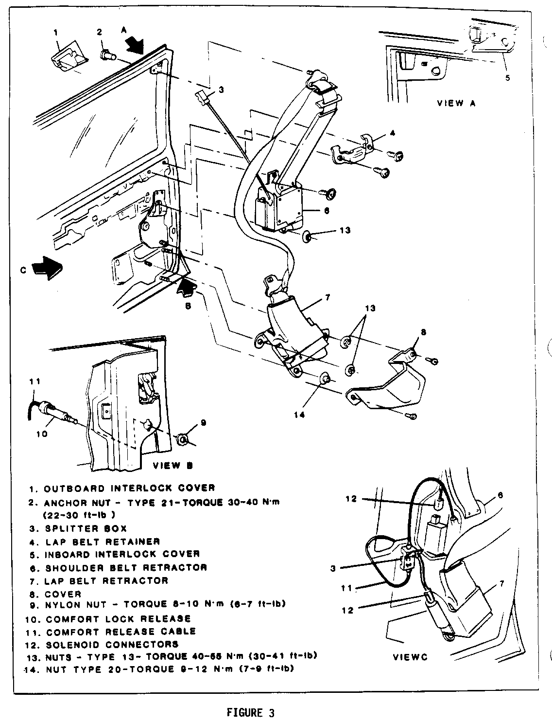
2. Remove plunger cable assembly (1) at splitter box (3) lower cable (See Figure 3).
3. a. Inspect by activating plunger. If it does not travel inward to a flush condition or does not return freely, plunger cable assembly must be replaced. Proceed to Step 4.
b. If plunger operates freely in both directions (when disconnected), using comfort lock to set or release is in comfort lock mechanism located in shoulder belt retractor. DO NOT ATTEMPT TO REPAIR. Replace complete belt assembly. Refer to 1987 Body Service Manual Section 9C or 9M.
4. Remove cover (8).
5. Disconnect lap belt retractor (7) on sedans only.
6. Disconnect shoulder belt retractor (6).
7. Disconnect electrical connectors (12) at solenoids.
8. Remove splitter box (3) from inner panel.
9. Remove bridge plate.
10. Carefully loosen water deflector.
11. Remove plunger cable assembly.
12. Reverse procedure to install new plunger cable assembly. Be sure to tape upper and lower cable assemblies to water deflector.
IMPORTANT: When working on any door compartment which requires partial or complete removal of the water deflector,any damage caused to the water deflector or any original holes in the deflector which do not line up with fastener locations in the door inner panel, must be repaired by applying waterproof tape to the affected area of the water deflector prior to installing the door trim panel. This is essential to prevent water entry into the passenger compartment and to maintain original sealing integrity.
WARRANTY INFORMATION
Right Side Left Side ---------- --------- Labor Operation to Replace Plunger and Cable Assembly: (Includes R&R C9040 C9041 R&R of Door Trim)
Labor Time: .9 Hour .9 Hour


General Motors bulletins are intended for use by professional technicians, not a "do-it-yourselfer". They are written to inform those technicians of conditions that may occur on some vehicles, or to provide information that could assist in the proper service of a vehicle. Properly trained technicians have the equipment, tools, safety instructions and know-how to do a job properly and safely. If a condition is described, do not assume that the bulletin applies to your vehicle, or that your vehicle will have that condition. See a General Motors dealer servicing your brand of General Motors vehicle for information on whether your vehicle may benefit from the information.
