SERVICE MANUAL UPDATE SEC. 5E1 (ABS) VALUE TEST CHARTS

SUBJECT: SERVICE MANUAL UPDATE 5E-l ANTILOCK BRAKE SYSTEM DIAGNOSTIC INLET/OUTLET VALVE TEST CHARTS REVISED
MODELS AFFECTED: 1991 BONNEVILLE MODELS
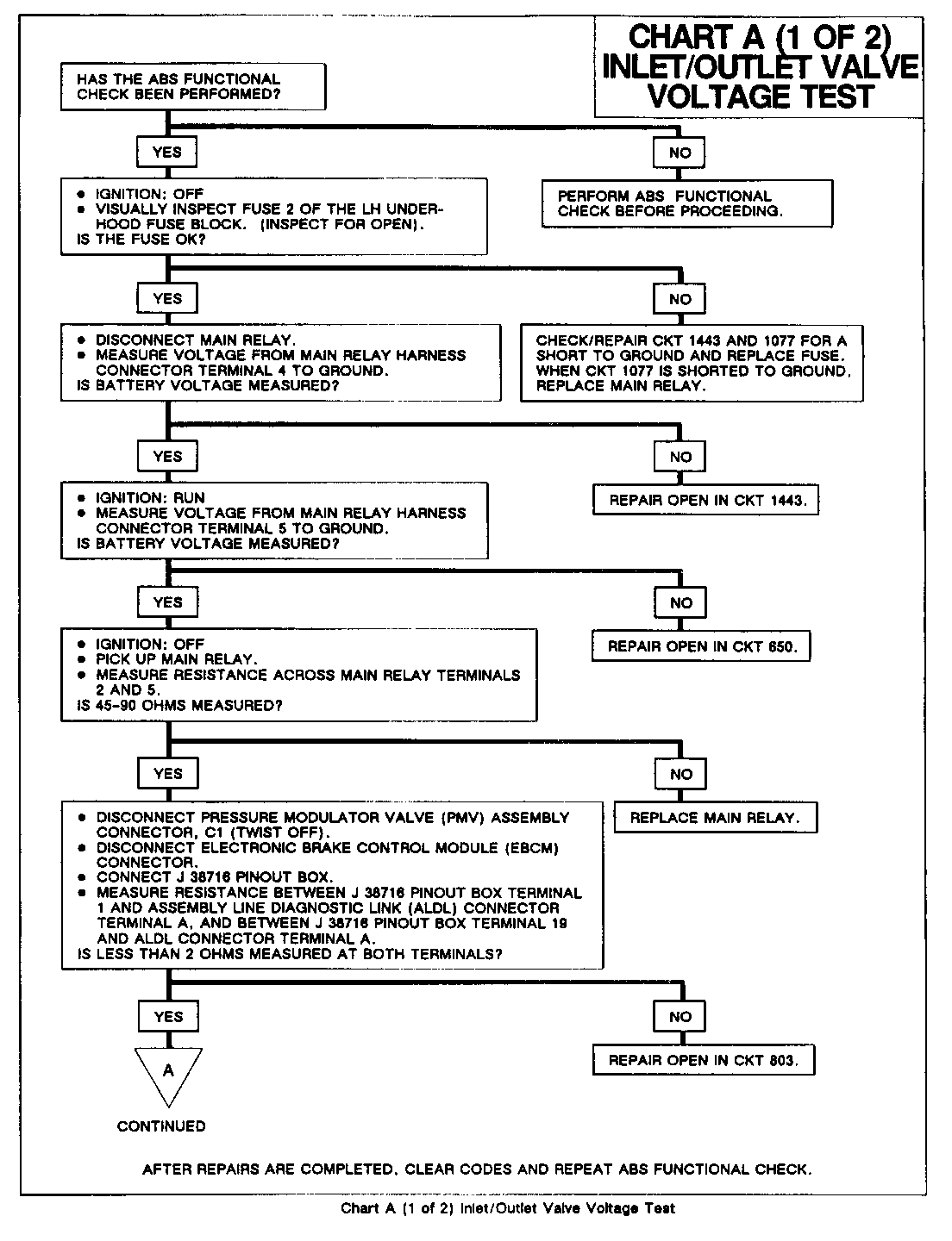
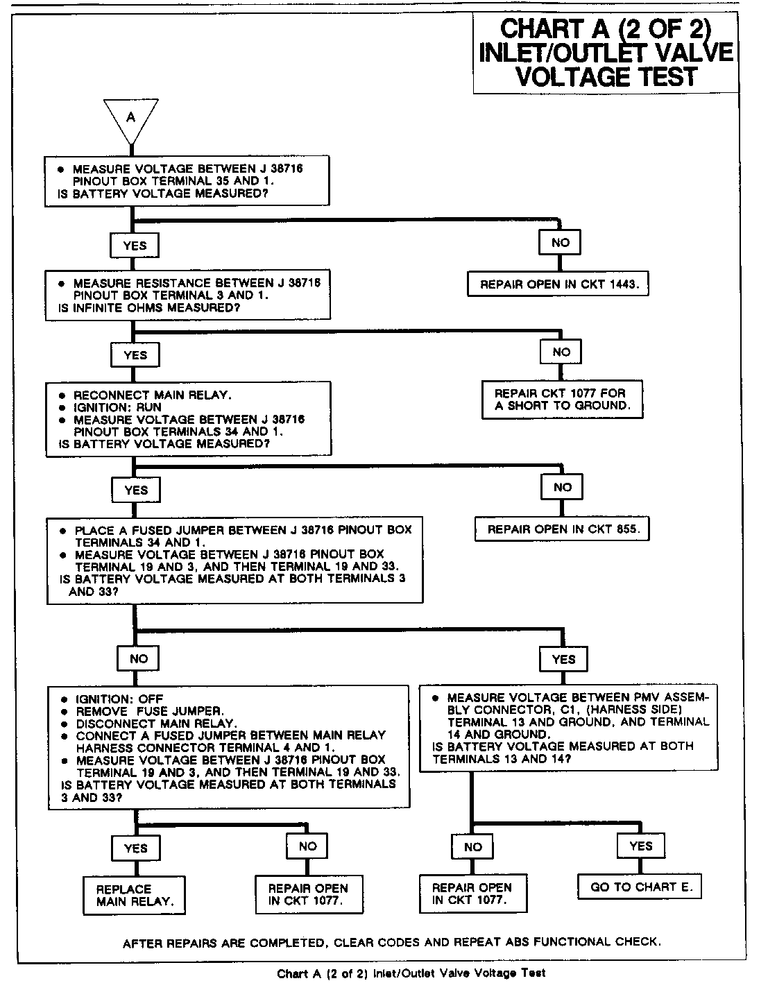
Delete charts A Inlet/Outlet Valve Circuit Tests on pages 5E1-11, 5E1-12 and 5E1-13.
They have been replaced with the following two charts:
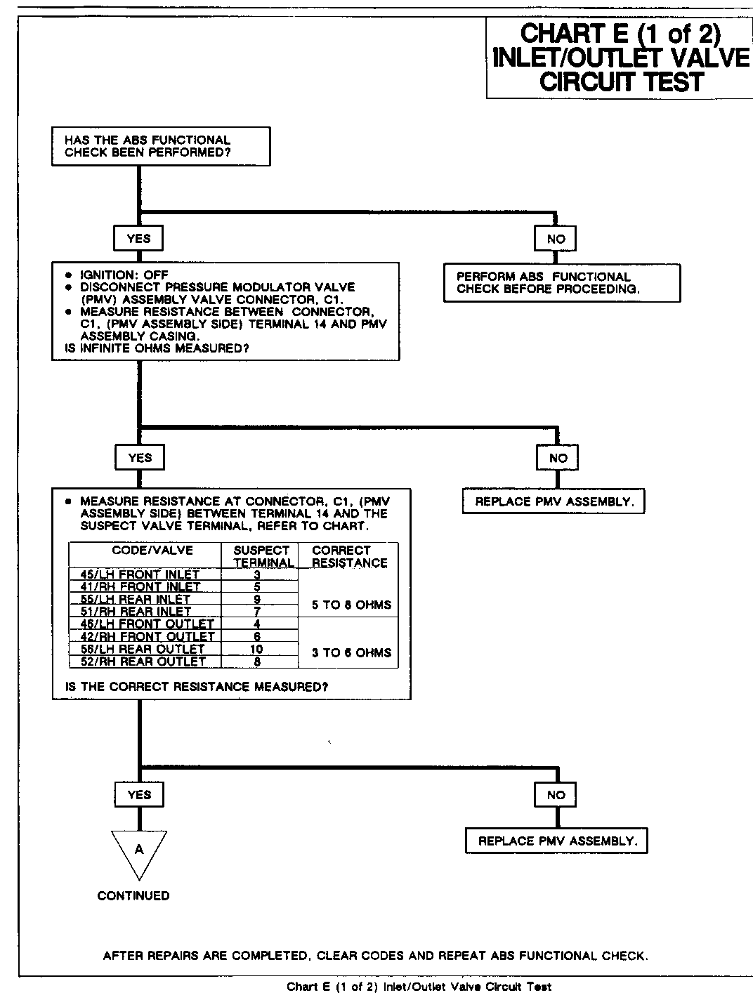
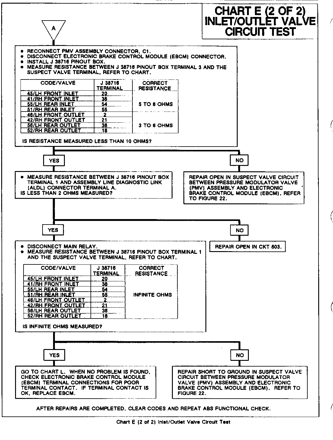
Revised Chart A Inlet/Outlet Valve Voltage Test - Additional Chart E Inlet/Outlet Valve Circuit Test. These two diagnostic charts have been revised to be more inclusive.
CHART E
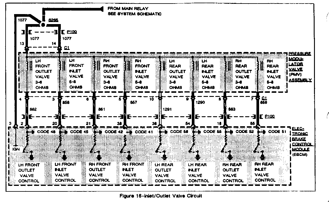
INLET/OUTLET VALVE CIRCUIT TEST ------------------------------- CIRCUIT OPERATION ----------------- Inlet Valves ------------ Voltage is applied to the normally open inlet valves whenever the main relay is energized. An inlet valve closes when the electronic brake control module (EBCM) supplies a ground path at the inlet valve control terminal. The EBCM closes an inlet valve for short periods to maintain (hold) or reduce pressure at a particular wheel during ABS braking.
Outlet Valves
The normally closed outlet valves operate similarly to the inlet valves, except that when the EBCM grounds an outlet valve, the valve opens instead of closes. The EBCM opens an outlet valve for short periods to reduce pressure at a particular wheel during ABS braking.
VALVE MODES
Pressure Increase
The pressure increase position is the operating valve position for normal (non-ABS) braking. The EBCM does not energize either valve, leaving the inlet valve open and the outlet valve closed.
Pressure Hold
The pressure hold position occurs when the EBCM first notices an abnormal hydraulic pressure increase. This signifies an impending wheel lockup condition. The EBCM closes the corresponding inlet valve in an attempt to avoid any additional hydraulic pressure increase (avoiding an ABS braking condition).
Pressure Reduce
During a wheel lockup condition, the EBCM close the inlet valve while pulsing open the outlet valve. This decreases hydraulic pressure at a specific wheel without decreasing overall system pressure. The reduced hydraulic pressure allows greater wheel spin, eliminating the wheel lockup condition.
Test Description
This test checks for proper inlet and outlet valve operation. The wheel brake behavior must be checked to verify the valves hydraulic effectiveness. This is accomplished using the TECH 1 to actuate the valves.
Failure Conditions
Code 41, 42, 45. 46. 51, 52, 55, or 56 sets when the electronic brake control module (EBCM) detects an open or short to ground in the respective inlet or outlet valve circuit.
General Motors bulletins are intended for use by professional technicians, not a "do-it-yourselfer". They are written to inform those technicians of conditions that may occur on some vehicles, or to provide information that could assist in the proper service of a vehicle. Properly trained technicians have the equipment, tools, safety instructions and know-how to do a job properly and safely. If a condition is described, do not assume that the bulletin applies to your vehicle, or that your vehicle will have that condition. See a General Motors dealer servicing your brand of General Motors vehicle for information on whether your vehicle may benefit from the information.
