SERVICE MANUAL UPDATE-SEC.8A ELECT. SYS/ELECT DIAG REVISION

SUBJECT: ELECTRICAL SYSTEMS/SERVICE MANUAL UPDATE/ SECTION 8A ELECTRICAL DIAGNOSTIC REVISIONS
MODELS AFFECTED: 1992 BONNEVILLE MODELS
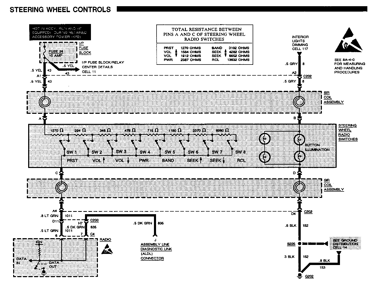
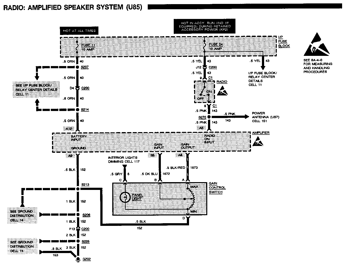
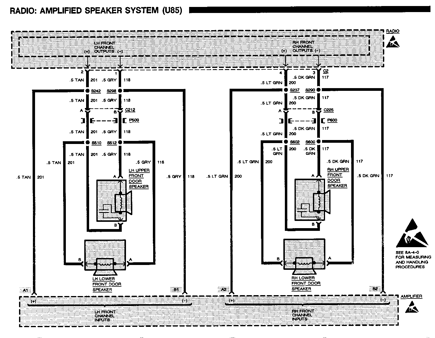
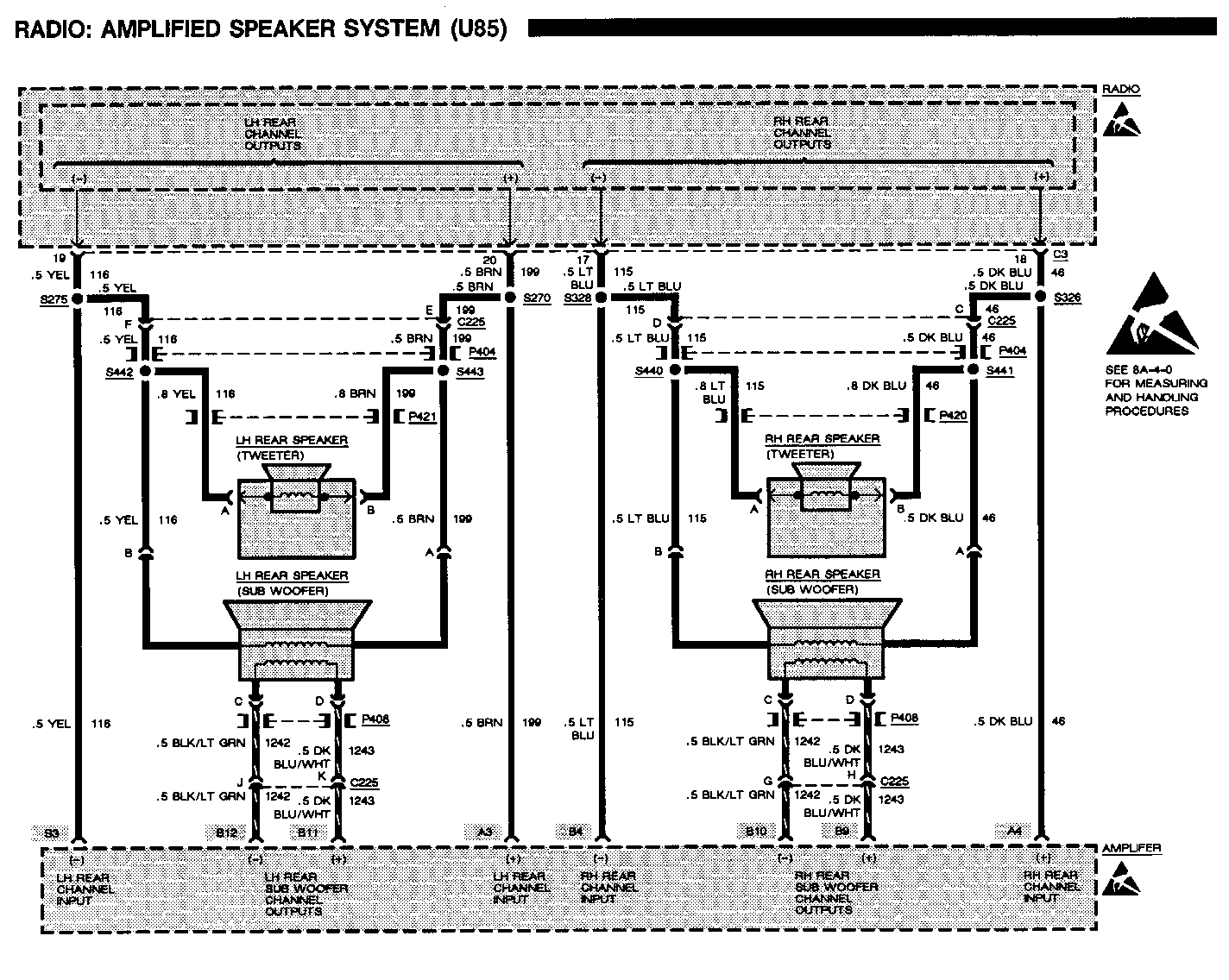
This bulletin provides LATE PRODUCTION AND DESIGN INFORMATION ranging from wire gauge and color changes to changing connector pinout identification and wiring routing changes.
The following information reflects current changes and revisions to the Electrical Systems/Service Manual Diagnostic Procedures:
1992 Bonneville SE
1992 Bonneville SSE/SSEi
Please update your Service Manual accordingly.
UPDATE CHANGE SUMMARY CARLINE: PONTIAC BONNEVILLE SE -------------------------------
Page(s) Revision ------- -------- 8A-14-5 8A-130-0 Change the .5 BLK (154) wire between the Door Lock Relay Assembly 8A-132-0 and Splice S289 to 2 BLK (154).
8A-14-2 Change the .8 BLK(153) wire between the Luggage Compartment Light 8A-114-2 Switch and Splice S400 to .8 BLK/WHT (153).
8A-14-2 Change the .8 BLK (153) wire between the Luggage Compartment Lid 8A-134-0 Release Actuator and Splice S400 to .8 BLK/WHT (153).
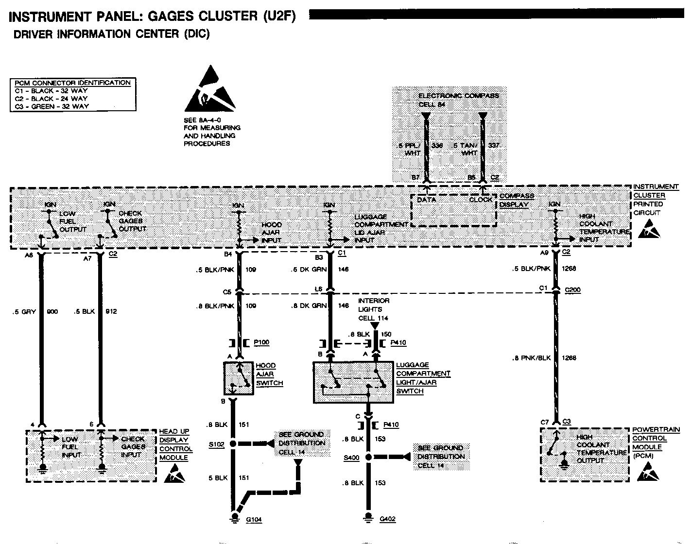
UPDATE CHANGE SUMMARY CARLINE: PONTIAC BONNEVILLE SSE/SSEi ------------------------------------- Page(s) Revision ------- -------- Contents Remove "(U5O)" from Cell 81 Instrument Panel: Gages Cluster (U2F) (U50).
8A-14-3 Change the .8 BLK (153) wire between the Luggage Compartment 8A-114-0 Light/Ajar Switch and Splice S400 to .8 BLK/WHT (153) wire.
8A-14-3 Change the .8 BLK (153) wire between the Luggage Compartment Lid 8A-134-0 Release Actuator and Splice S400 to .8 BLK/WHT (153) wire.
8A-14-7 Change the .5 BLK (154) wire between the Door Lock Relay Assembly 8A-130-0 and Splice S289 to 2 BLK (154). 8A-132-0
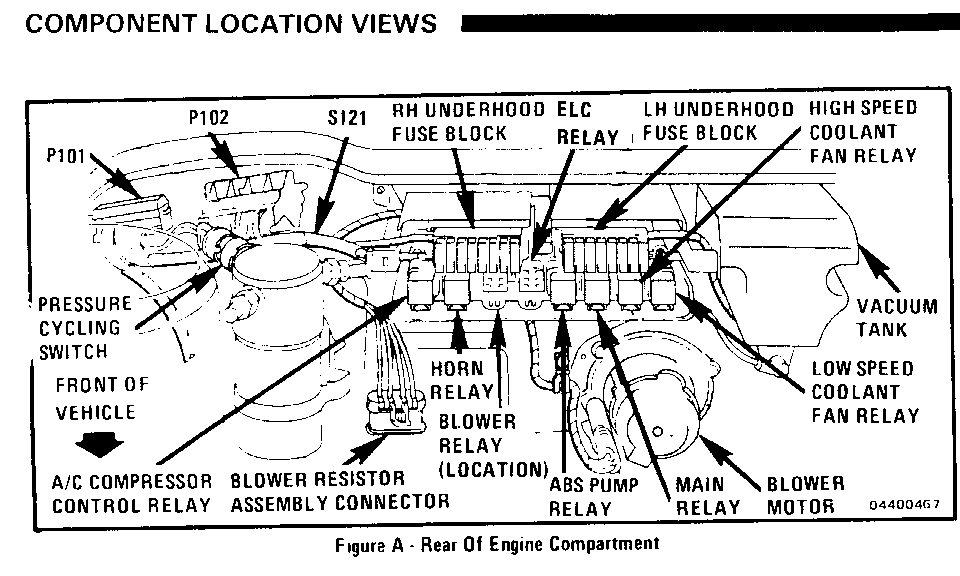
8A-42-1 In the Component Location Chart, add "201-5-A," in the Figure column, to the ELC Relay.
8A-44-3 Change the .8 BLK (884) wire between the Electronic Brake Control Module and Connector C410 to .5 BLK (884). Change the .8 RED (885) wire between the Electronic Brake Control Module and Connector C410 to .5 RED (885). Change the .8 BRN (882) wire between the Electronic Brake Control Module and Connector C410 to .5 BRN (882). Change the .8 WHT (883) wire between the Electronic Brake Control Module and Connector C410 to .5 WHT (883).
8A-68-1 Change the Defrost-A/C Valve Vacuum Actuator hose connector from 4 to 6. Change the Heater-A/C Bi-Level Valve Vacuum Actuator hose connectors from 6 to 4 and from 5 to 3. Change the O/S Air-Recirc. Valve Vacuum Actuator hose connector from 1 to 5.
8A-81-0 Remove "(U50)" from the top page header. through 8A-81-32
AIR CONDITIONING: BLOWER CONTROLS --------------------------------- ELECTRONIC AIR CONDITIONING (C68) --------------------------------- C: BLOWER FEEDBACK TEST ----------------------- Measure: RESISTANCE ------------------- At: HVAC PROGRAMMER CONNECTOR (Disconnected) -------------------------------------------- Conditions: -Ignition Switch: OFF -Connect a fused jumper across Blower Motor connector terminals A & B
Measure Correct For Between Resistance Diagnosis ------- ---------- --------- D2 (ORN) Less than 3 See 1 & Ground ohms
-If resistance is correct, check GRY/BLK (754) wire for a short to Battery. If wire is OK, replace HVAC Programmer.
1. Check Relay Center Fuse 1, ORN (761) and PPL (65) wires for an open or short to ground.
CIRCUIT OPERATION
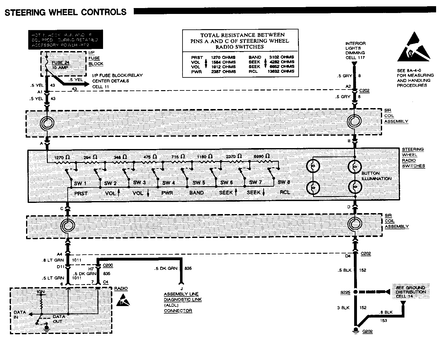
The Blower Motor control circuit consists of the following components: Blower Motor, HVAC Programmer, Blower Control Module, Heater And A/C Control Assembly and Steering Wheel Controls (if equipped).
The Blower's speed is determined by the voltage applied to the motor. At low Blower Motor speeds, the applied voltage is about 4 volts. As the voltage increases, the Blower Motor speed increases until the maximum Blower speed is reached. At maximum speed, the applied voltage is battery voltage.
Blower speed is controlled by the HVAC Programmer from temperature signal inputs and the operation mode of the Air Conditioning System. The system's driver selected operation mode is communicated to the HVAC Programmer from the Heater And A/C Control Assembly and Steering Wheel Controls (if equipped) through the E & C Data Line.
The Blower speed output from the HVAC Programmer is a continuously variable voltage. At minimum Blower speed, the output is 2-3 volts. At maximum Blower speed, the output is 6-8 volts.
The output signal from the HVAC Programmer is input to the Blower Control Module. An amplifier and driver circuit in the Blower Control Module supplies between 0 and 12 volts to run the Blower Motor. This same voltage is also used as a feedback signal to the HVAC Programmer to allow precise Blower Motor speed control.
COMPONENT LOCATION
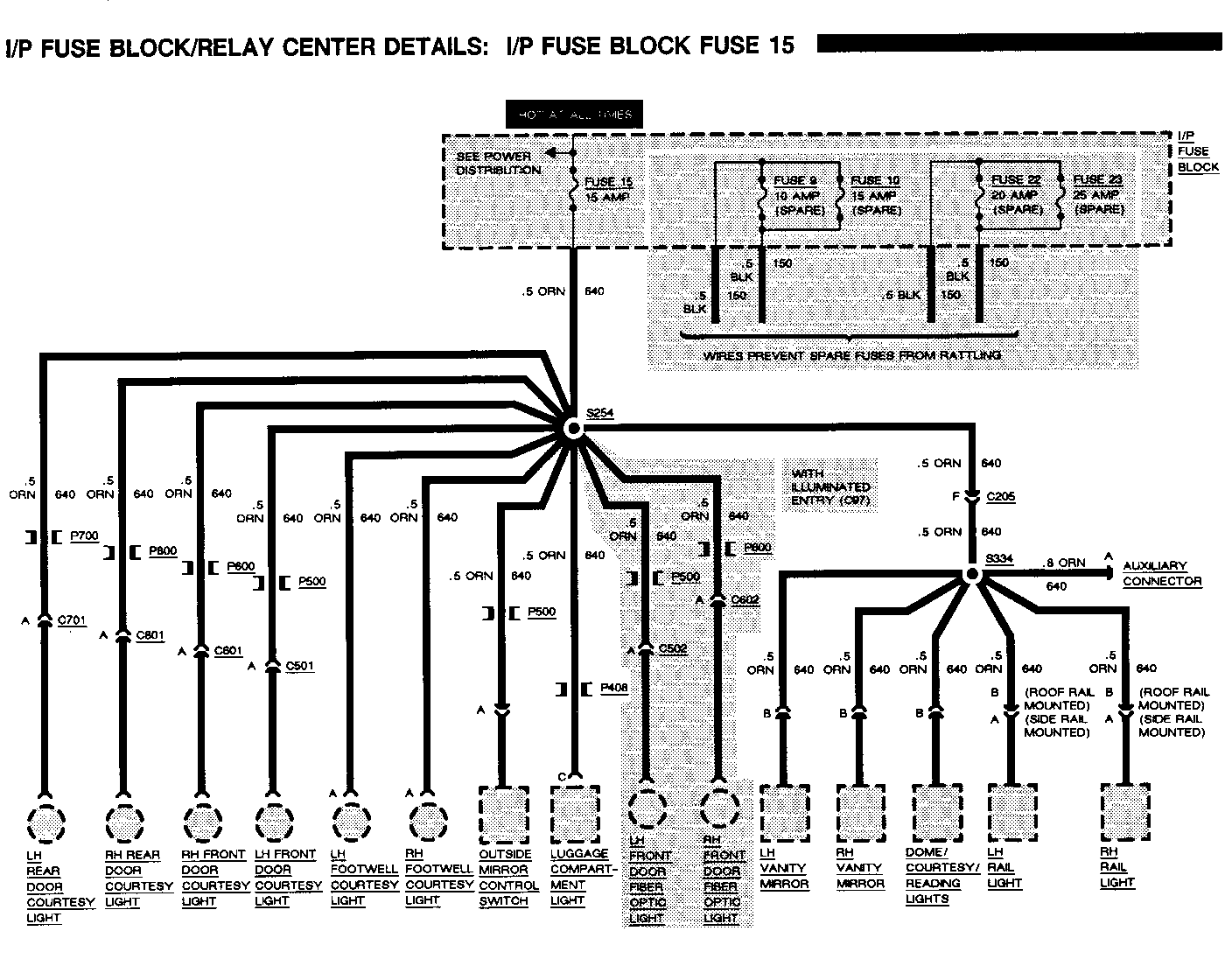
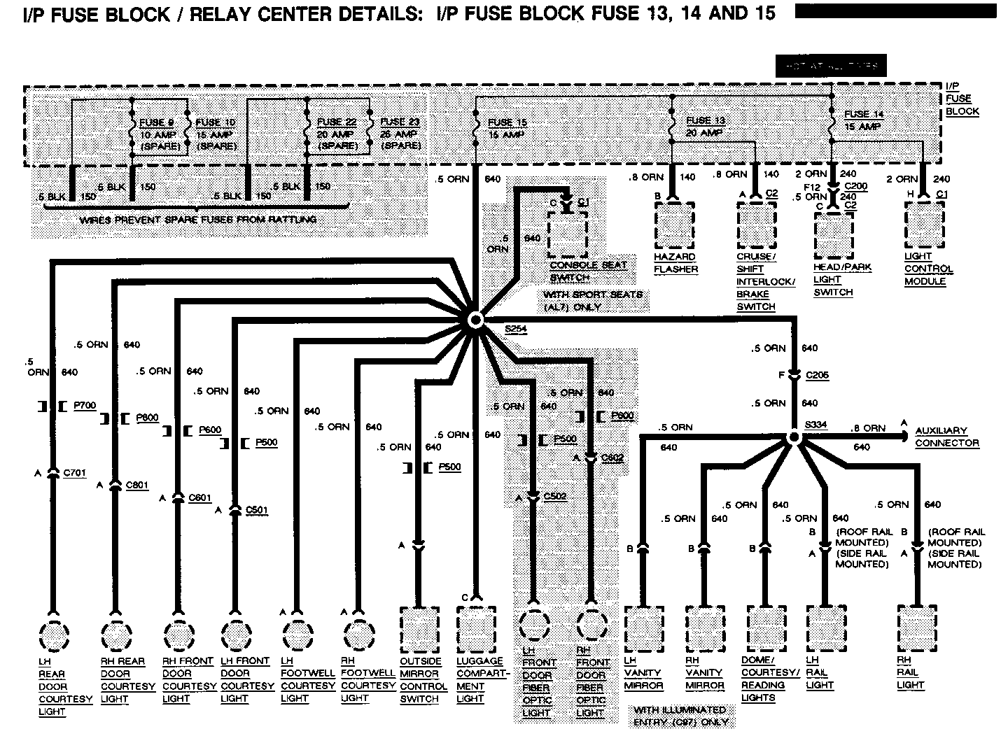
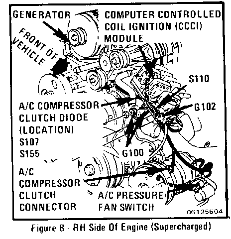
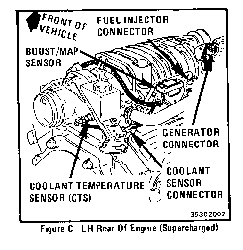
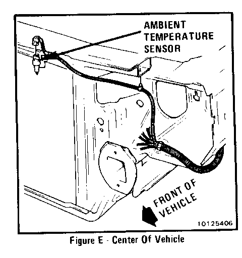
Item Description Page-Figure ----- ----------- ----------- I/P Fuse Block...... Behind LH side of I/P,left of steering column, behind trim panel ......................... 201-8-A C340 (10 cavities). LH front door sill, taped to composite harness. 201-12-C G202 ............... Below LH side of I/P, middle of shroud........ 201-8-E P500 ............... Front of LH front door....................... 201-15-A P600 ............... Front of RH front door....................... 201-15-A S225 ............... Composite harness, bottom of LH shroud... 201-8-E S254 ............... Composite harness, middle of LH shroud... 201-8-E S271 ............... Composite harness, middle of LH shroud, near grommet P500 ........................... 201-15-A S272 ............... Composite harness, middle of LH shroud, near grommet P500 ............................ 201-15-A S288 ............... Composite harness, bottom of LH shroud... 201-8-E
POWER MIRRORS (DC6, DD9)
TROUBLESHOOTING HINTS
-Try the following checks before doing the System Check.
1. Check I/P Fuse Block Fuse 15 by checking for operation of the LH Footwell Courtesy Light.
2. Check ground by checking for Power Window operation (if equipped).
- Go to System Check for a guide to normal operation.
- Go to System Diagnosis for diagnostic tests.
SYSTEM CHECK
- Use the System Check Table as a guide to normal operation.
- Refer to System Diagnosis for a list of symptoms and diagnostic steps.
SYSTEM CHECK TABLE
ACTION NORMAL RESULT ------ ------------- Put Mirror Select LH Outside Mirror Switch in LEFT moves smoothly up- position ward and downward Operate Outside Mirror Control Switch in UP and DOWN positions
Operate Outside LH Outside Mirror Mirror Control moves smoothly to Switch in the LEFT the left and right and RIGHT positions
Put Mirror Select RH Outside Mirror Switch in RIGHT moves smoothly up- position ward and downward Operate Outside Mirror Control Switch in UP and DOWN positions
Operate Outside RH Outside Mirror Mirror Control moves smoothly to Switch in the LEFT the left and right and RIGHT positions
- Refer to System Diagnosis when a result is not normal.
SYSTEM DIAGNOSIS
- Diagnostic tests for the symptoms listed in the following table are listed after the table.
SYMPTOM TABLE
A: Both mirrors do not operate in any mode
B: LH mirror does not operate in one or more modes
C: RH mirror does not operate in one or
POWER MIRRORS (DC6, DD9)
A: BOTH MIRRORS DO NOT OPERATE IN ANY MODE ------------------------------------------ Connect: TEST LAMP ------------------ At: OUTSIDE MIRROR CONTROL SWITCH CONNECTOR (Disconnected) ---------------------------------------------------------- Connect Correct For Between Result Diagnosis ------- ------- --------- A (ORN) Test Lamp See 1 & Ground lights
A (ORN) Test Lamp & H (BLK) lights See 2
- If the results are correct, replace the Outside Mirror Control Switch.
1. Check/repair ORN (640) wire.
2. Check/repair BLK (152) wire.
B: LH MIRROR DOES NOT OPERATE IN ONE OR MORE MODES -------------------------------------------------- Measure: TEST LAMP ------------------ At: OUTSIDE MIRROR CONTROL SWITCH TERMINALS (Connected) ------------------------------------------------------- Conditions: ----------- - Mirror Select Switch: LEFT
- Mirror Position Switch: Hold UP and DOWN
Connect Correct For Between Result Diagnosis ------- ------- --------- D (YEL) & Test Lamp See 1 C (LT BLU) Lights
- Hold Mirror Select Switch in LEFT and RIGHT positions
B (WHT) & Test Lamp C(LT BLU) lights See 1
- If all results are correct, check wiring and connectors for shorts or opens (see schematic). If all are OK, replace LH Outside Mirror Drive Unit.
1. Replace Outside Mirror Control Switch.
C: RH MIRROR DOES NOT OPERATE IN ONE OR MORE MODES -------------------------------------------------- Measure: TEST LAMP ------------------ At: OUTSIDE MIRROR CONTROL SWITCH CONNECTOR (Connected) ------------------------------------------------------- Conditions: ----------- - Mirror Select Switch: RIGHT
- Mirror Position Switch: Hold UP and DOWN
Connect Correct For Between Result Diagnosis ------- ------- --------- E (YEL) & Test Lamp F (LT BLU) lights See 1
- Hold Mirror Select Switch in LEFT and RIGHT positions
G (WHT) & Test Lamp F (LT BLU) lights See 1
- If all results are correct, check wiring and connectors for shorts or opens (see schematic). If all are OK, replace RH Outside Mirror Drive Unit.
1. Replace Outside Mirror Control Switch.
CIRCUIT OPERATION
The Power Mirrors are adjusted from the interior of the vehicle by moving the Outside Mirror Control Switch in the desired direction.
Each Outside Mirror has two reversible motors. One adjusts the mirror view up and down, the other adjusts the mirror view right and left. The driver operates either an Up-Down Switch or Left-Right Switch to control the polarity of the voltage to the motors. The Mirror Select Switch directs these control voltages to either the RH or LH Outside Mirror.
With the Mirror Select Switch in the LH position and the Mirror Position Switch held in the UP position, battery voltage from the ORN wire is applied through the UP contact of the Mirror Position Switch to the YEL wire at terminal D and to the Up-Down Motor in the LH Outside Mirror. The LH Outside Mirror Up-Down Motor has a path to ground through the LT GRN and LT BLU wires at terminal C, through the Mirror Select Switch, the UP contact of the Mirror Position Switch and the BLK wire. The LH Motor runs and turns the mirror up.
When the Mirror Position Switch is pushed to the down position, the LH Motor receives voltage; however, the polarity is reversed. The YEL wire is now grounded and voltage is applied to the motor through the LT GRN and LT BLU wires. The motor runs in the opposite direction.
The LH Left-Right Motor operates similarly. When the Mirror Position Switch is moved to the LEFT position, battery voltage from the ORN wire is applied through the LH contacts of the Mirror Select Switch to the LT BLU wire at terminal C and the Left-Right Motor in the LH Outside Mirror. The LH Outside Mirror motors are grounded through the WHT wire at terminal B, the Left-Right Switch and BLK wire. The LH Motor runs and tums the mirror to the left.
If the Left-Right Switch is pushed to the RIGHT position, the same Motor receives voltage; however, the polarity is reversed. With the LT BLU wire grounded, voltage is now applied to the motor through the WHT wire. The Motor runs in the opposite direction.
The RH Outside Mirror works similarly to the LH Outside Mirror when the Mirror Select Switch is moved to the RH position and the Up-Down and Left-Right Switches are operated.
General Motors bulletins are intended for use by professional technicians, not a "do-it-yourselfer". They are written to inform those technicians of conditions that may occur on some vehicles, or to provide information that could assist in the proper service of a vehicle. Properly trained technicians have the equipment, tools, safety instructions and know-how to do a job properly and safely. If a condition is described, do not assume that the bulletin applies to your vehicle, or that your vehicle will have that condition. See a General Motors dealer servicing your brand of General Motors vehicle for information on whether your vehicle may benefit from the information.
