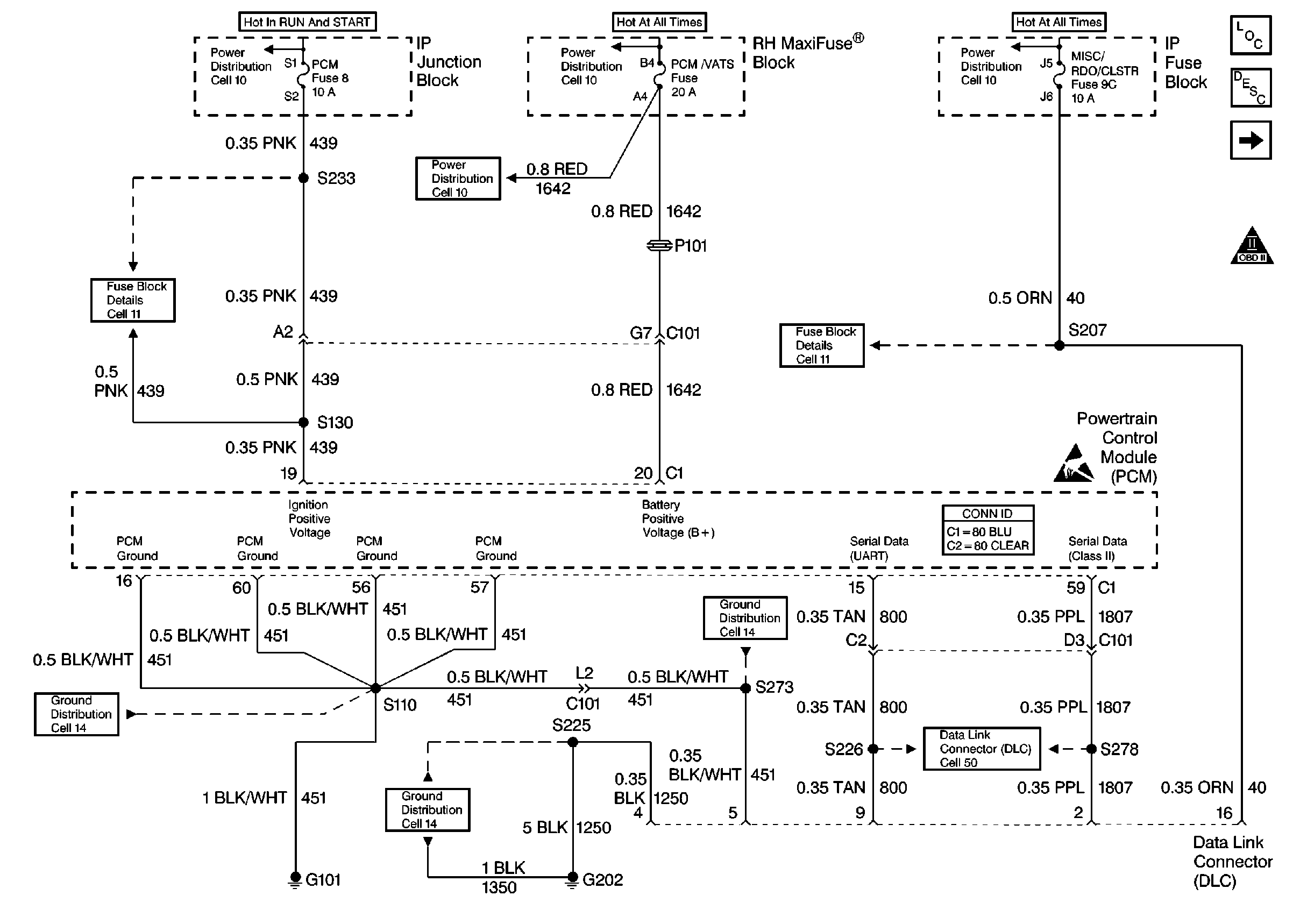
| Figure 1: |
Cell 20: PCM Power, Grounds and DLC
|
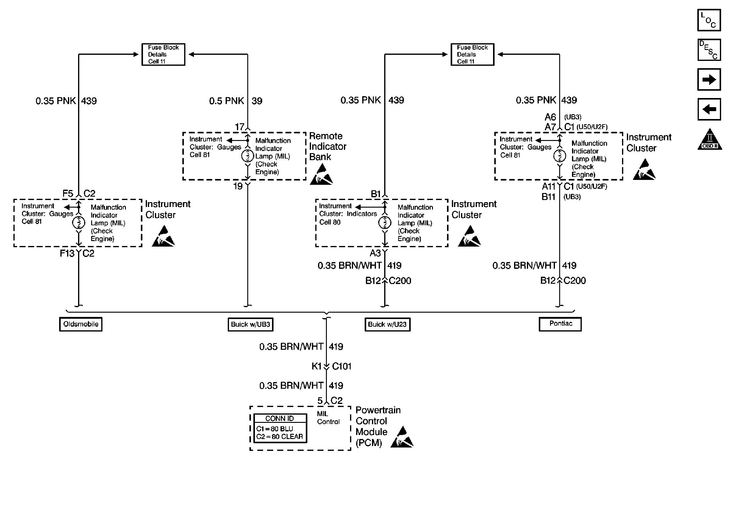
| Figure 2: |
Cell 20: MIL Control
|
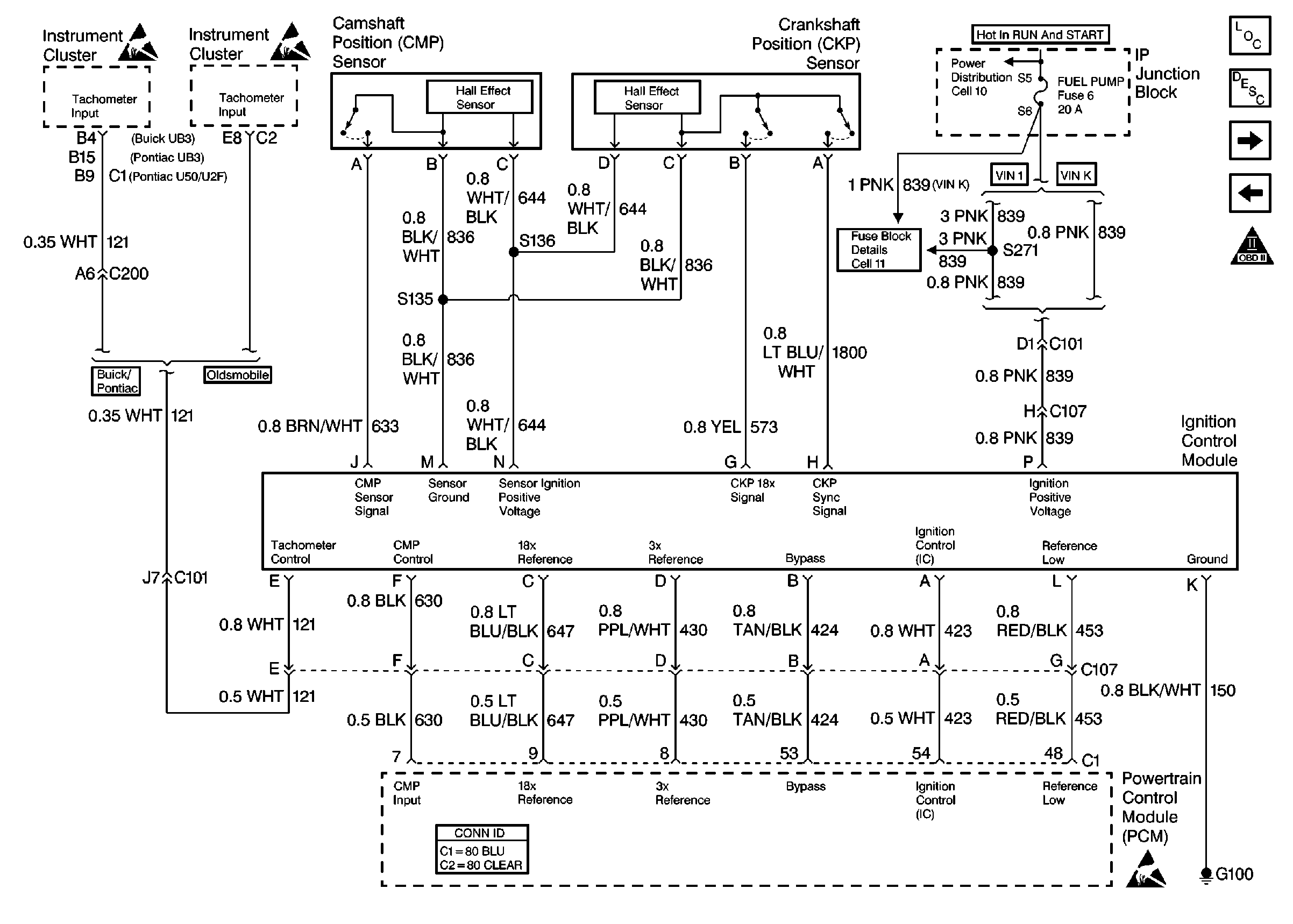
| Figure 3: |
Cell 20: Ignition Control Module
|
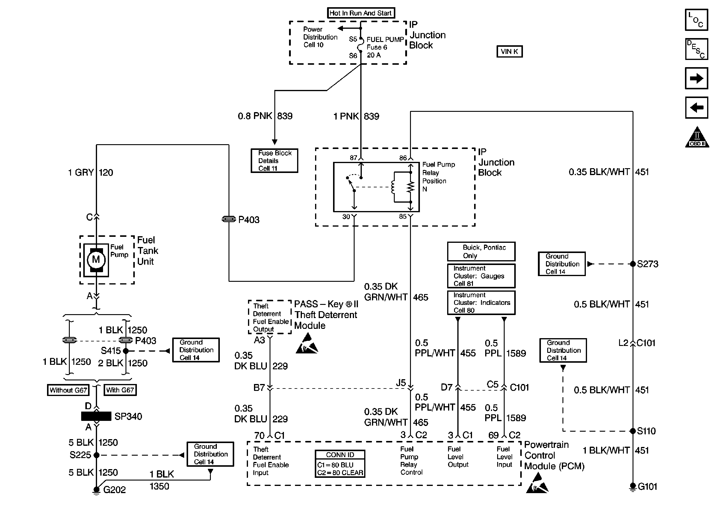
| Figure 4: |
Cell 20: Fuel Control (VIN K)
|
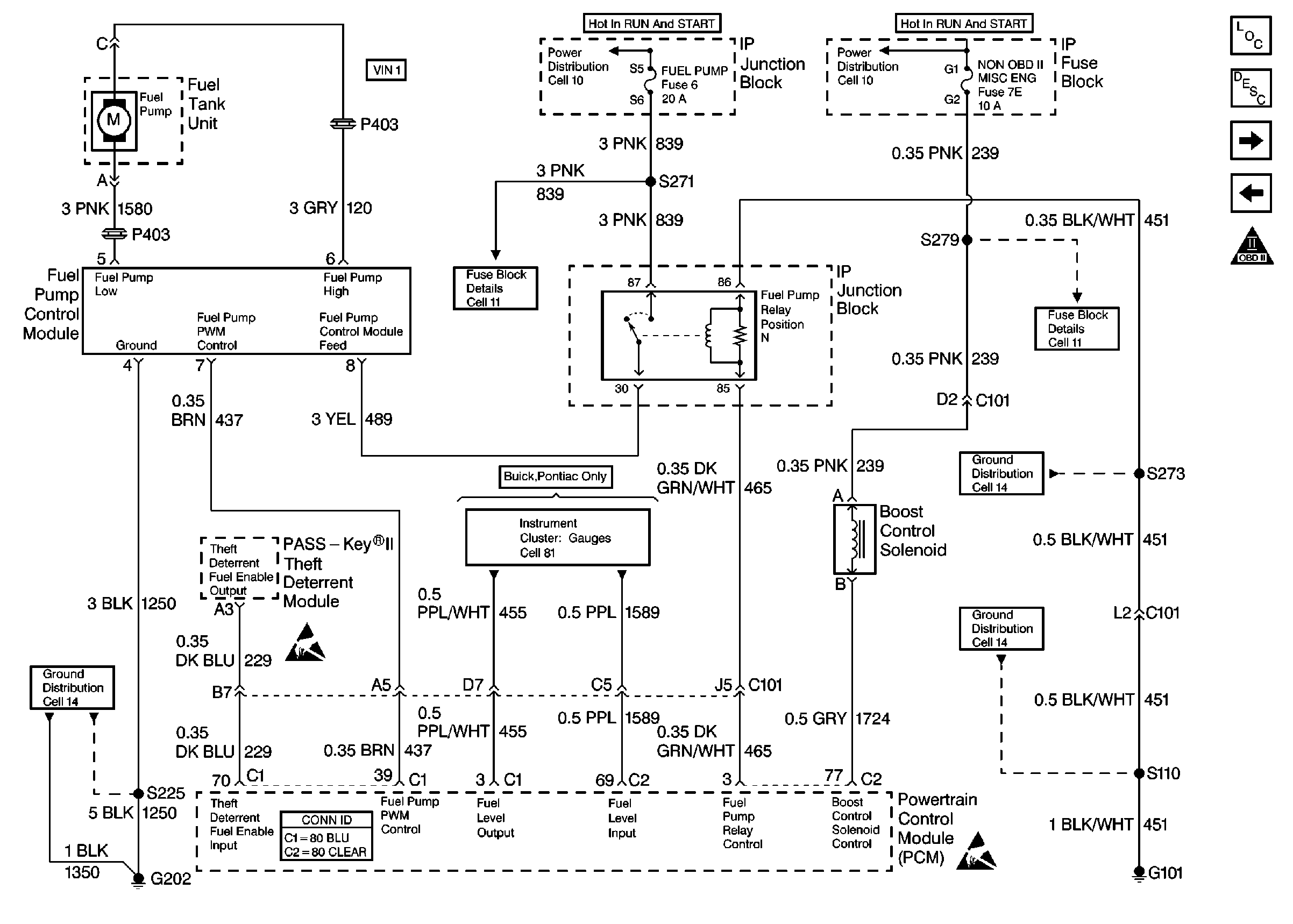
| Figure 5: |
Cell 20: Fuel Control (VIN 1)
|
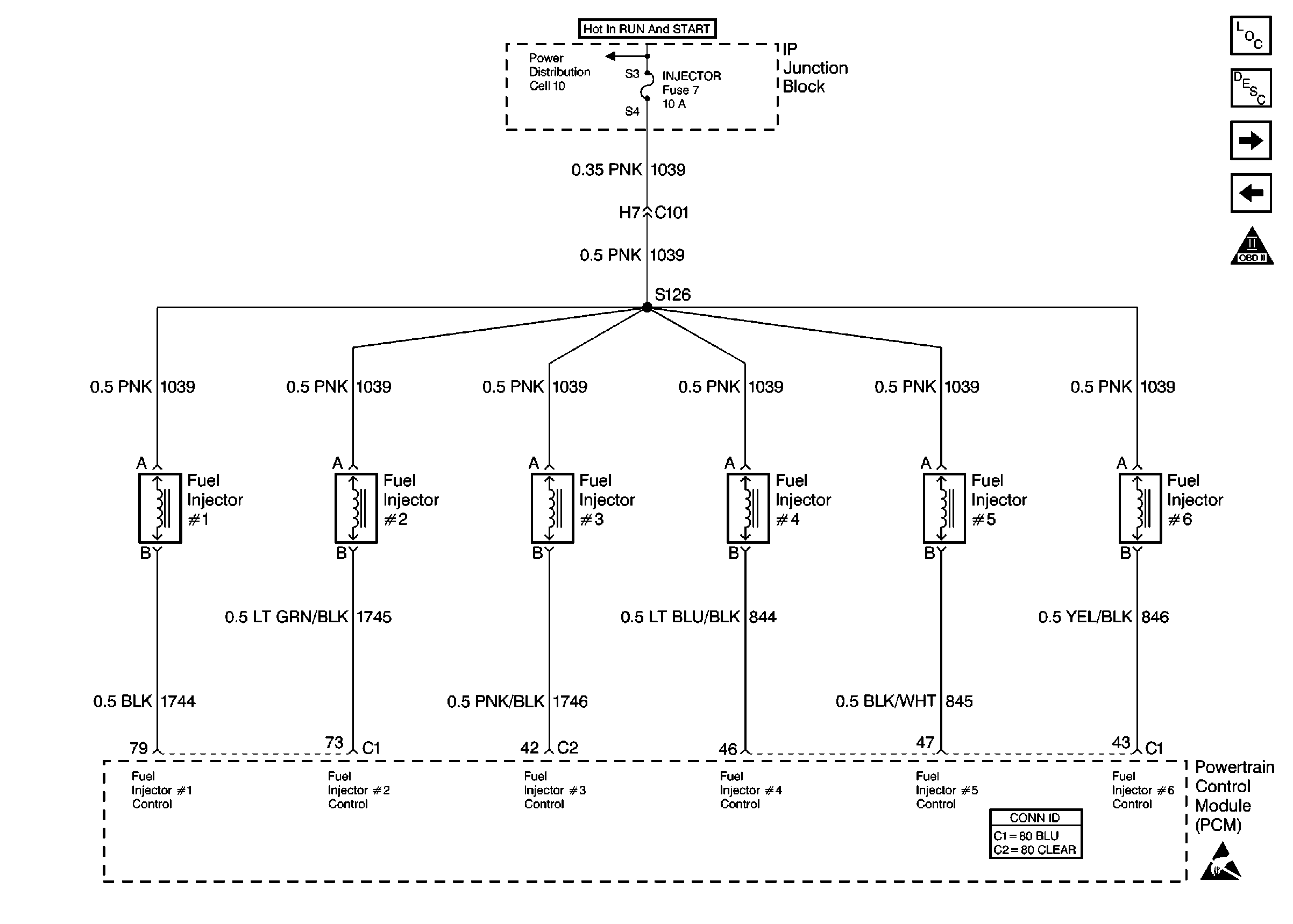
| Figure 6: |
Cell 20: Fuel Injectors
|
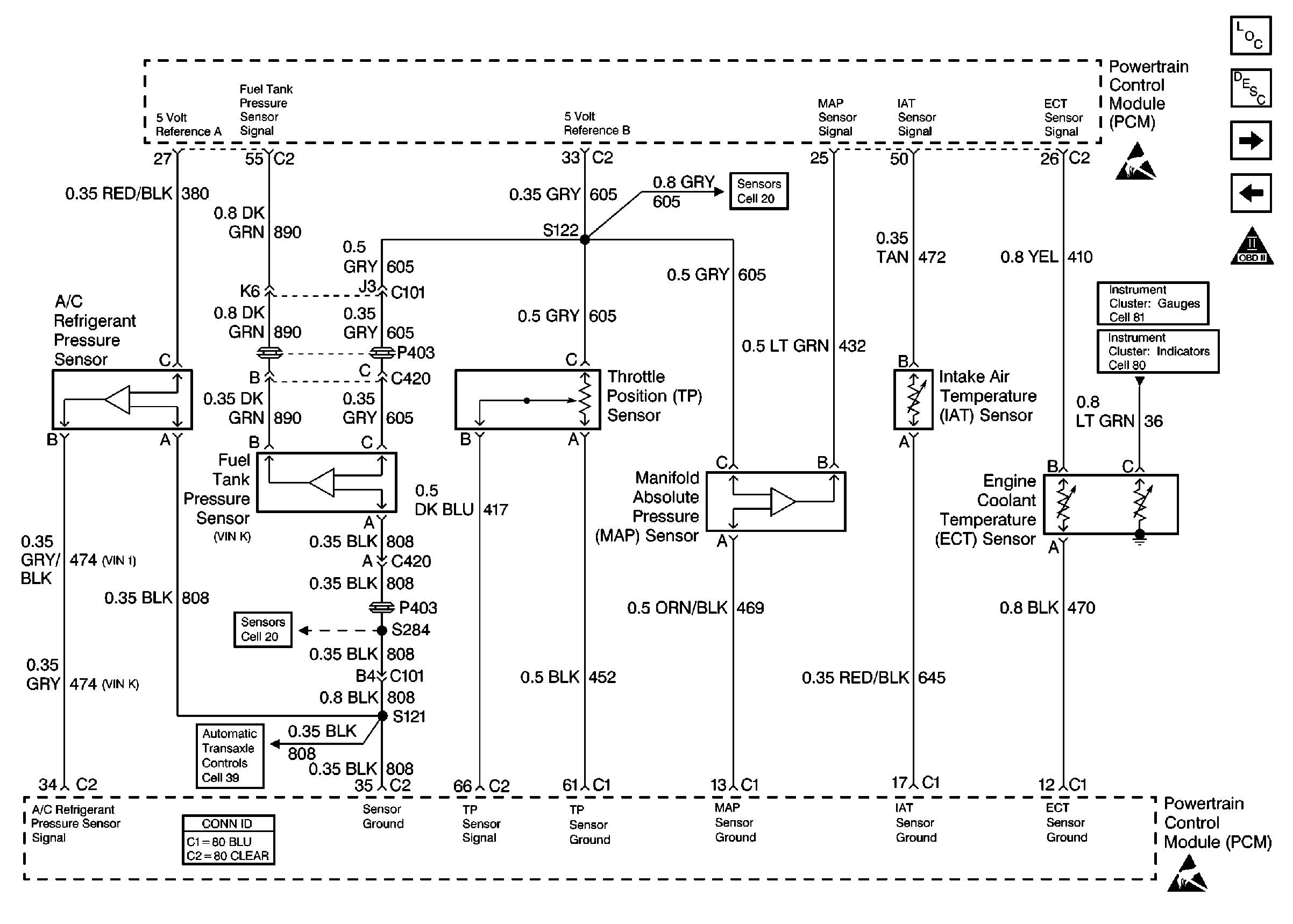
| Figure 7: |
Cell 20: Sensors
|
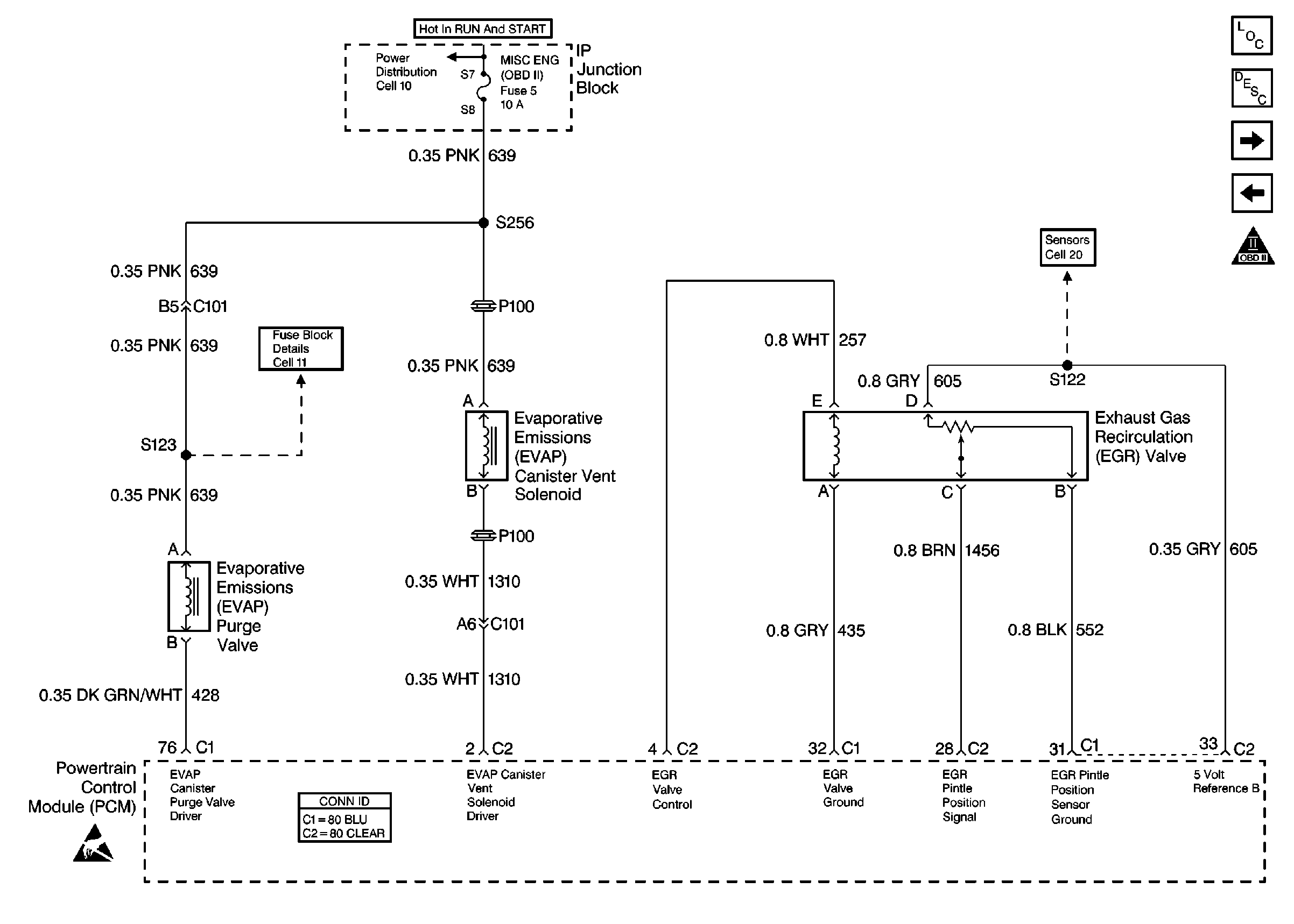
| Figure 8: |
Cell 20: EGR Valve, EVAP System
|
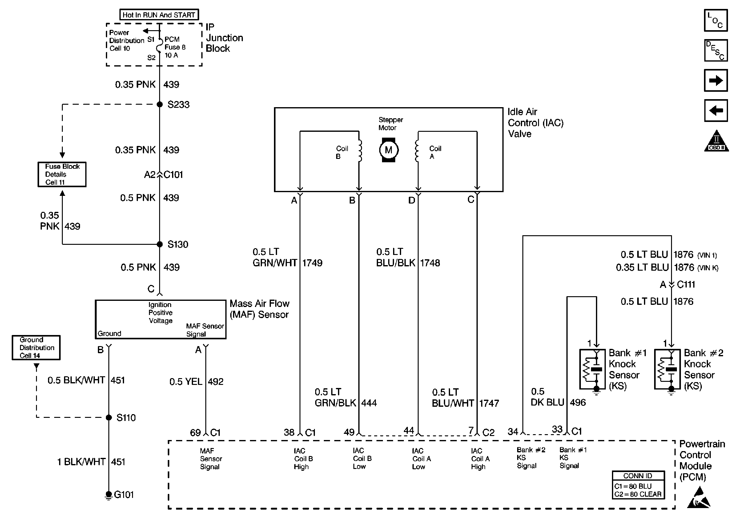
| Figure 9: |
Cell 20: MAF, IAC, Knock Sensors
|
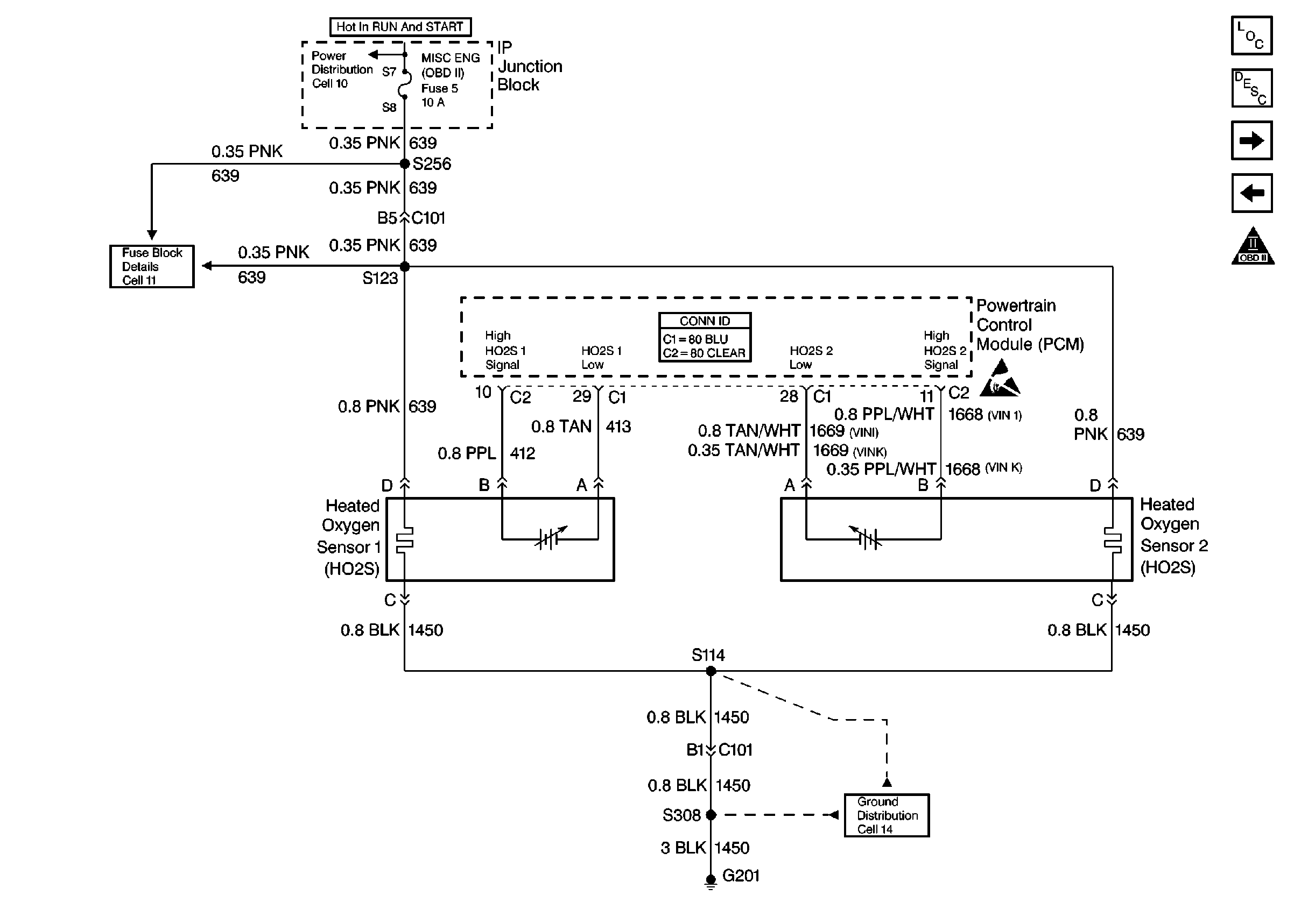
| Figure 10: |
Cell 20: Heated Oxygen Sensors
|
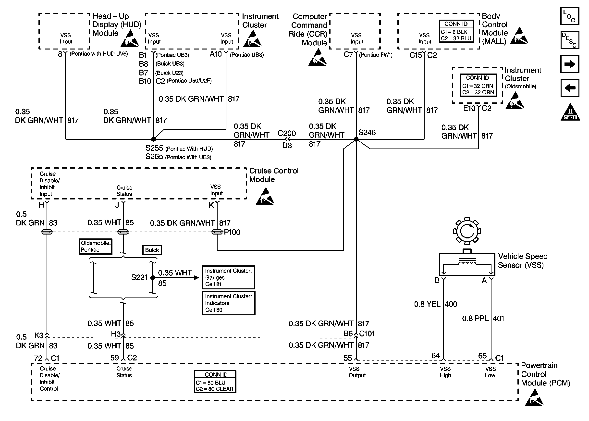
| Figure 11: |
Cell 20: VSS, Cruise Control Module
|
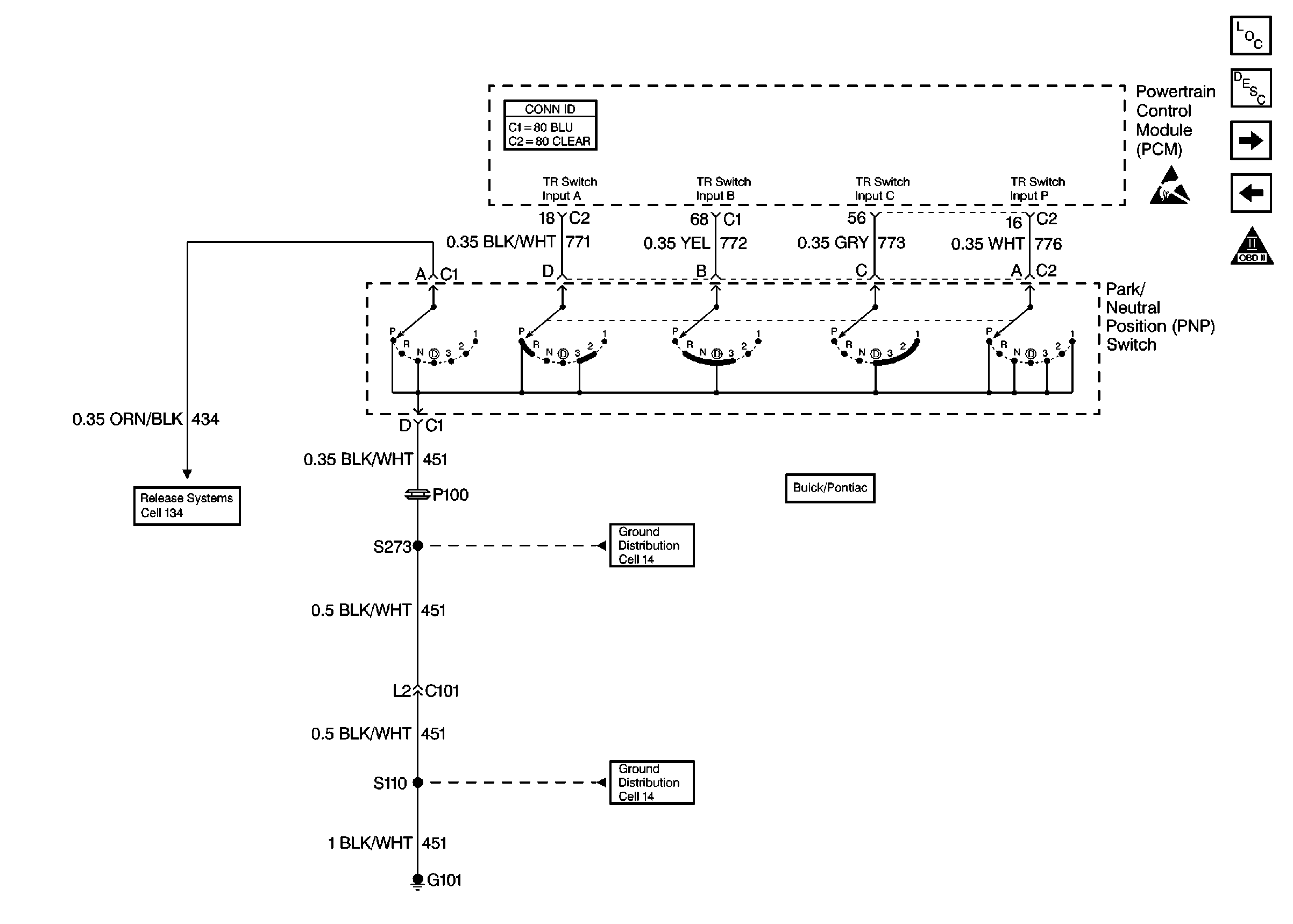
| Figure 12: |
Cell 20: Park/Neutral Position (PNP) Switch
|
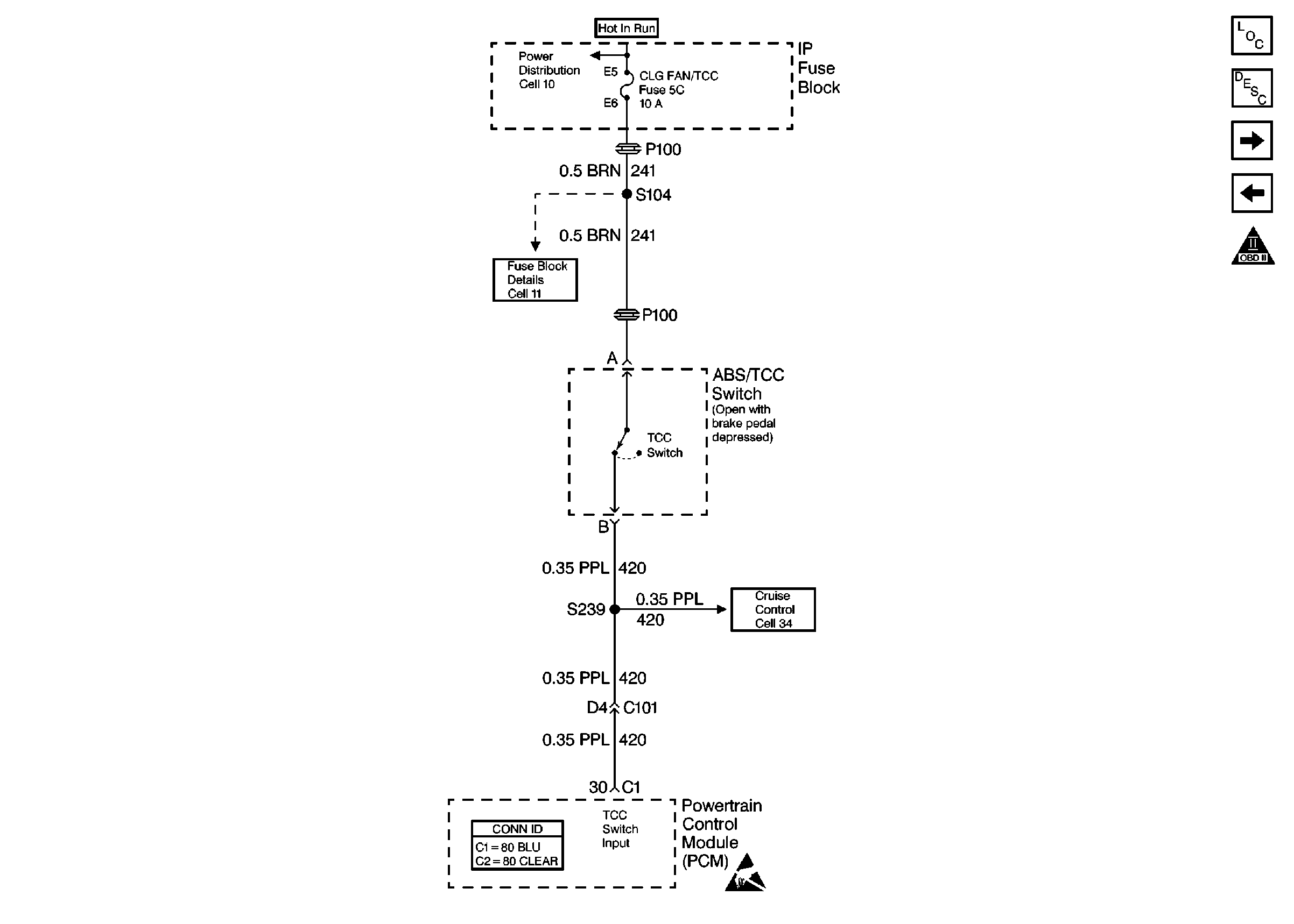
| Figure 13: |
Cell 20: TCC Switch
|
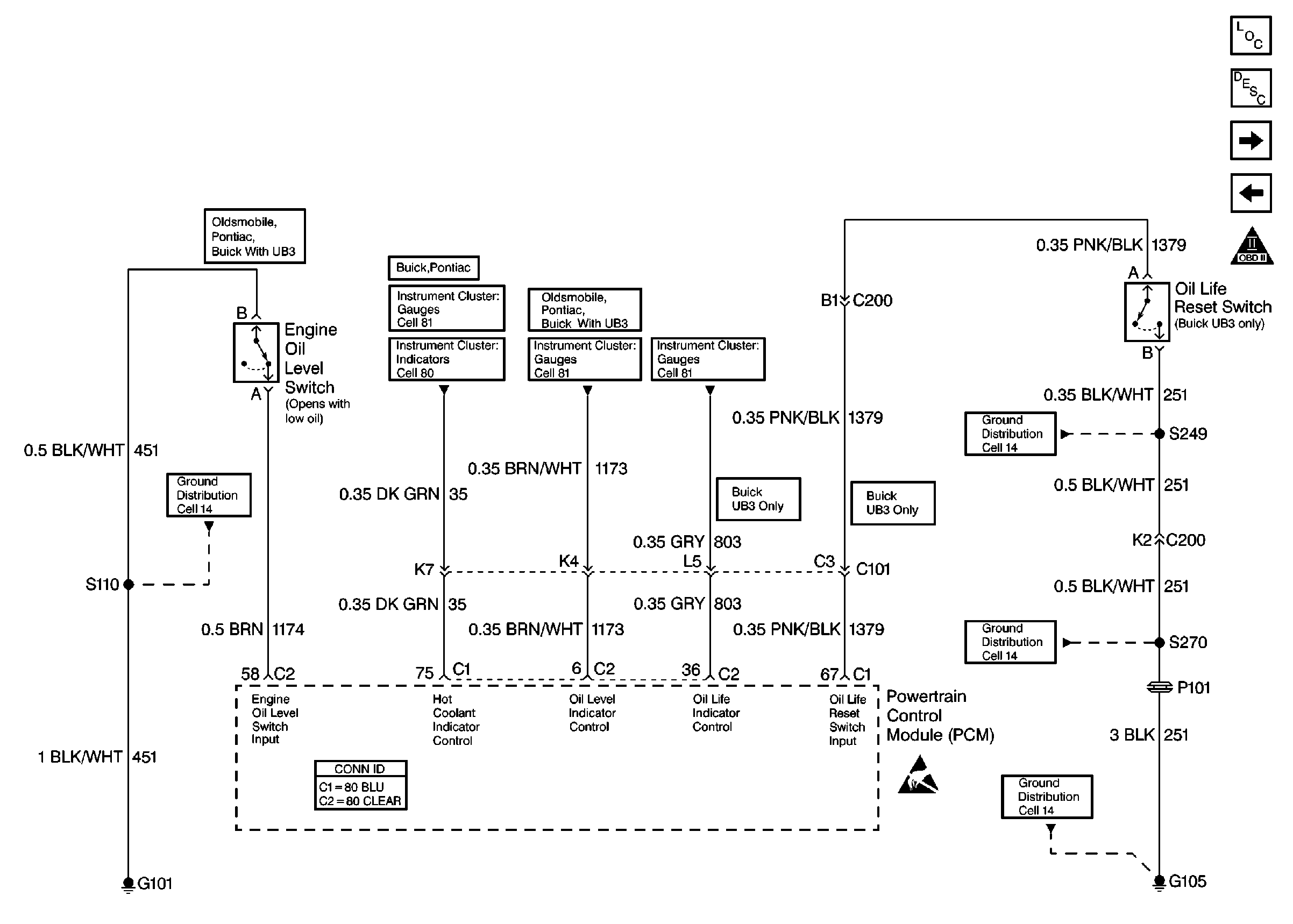
| Figure 14: |
Cell 20: Oil Life, Oil Level Switches
|
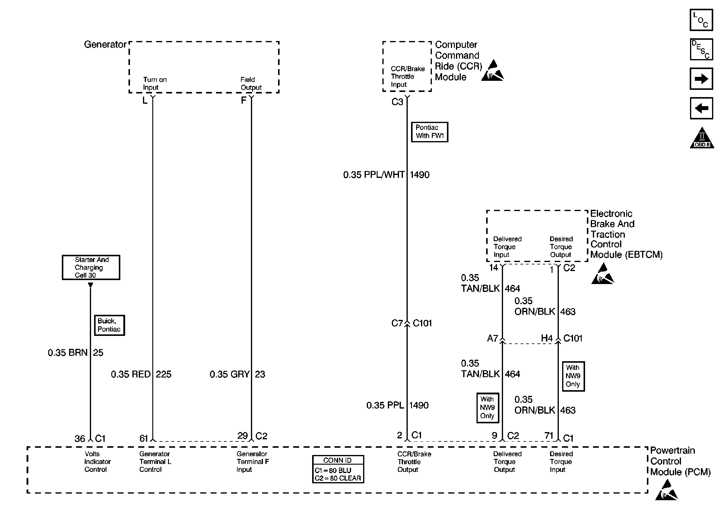
| Figure 15: |
Cell 20: Generator, CCR, EBTCM
|
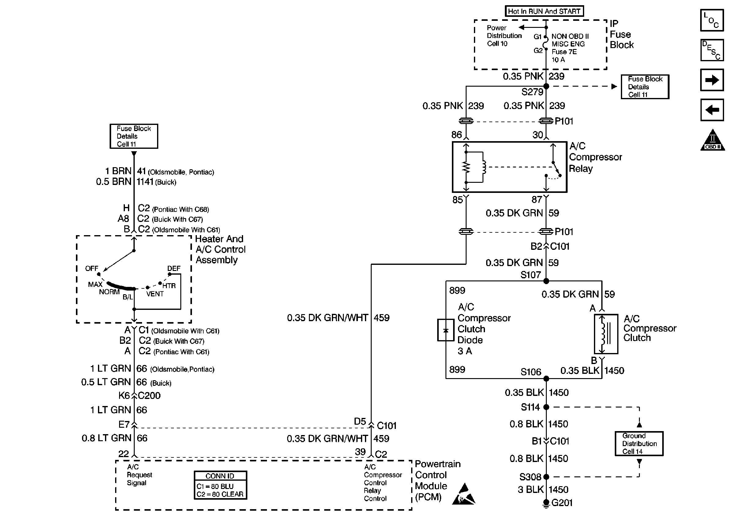
| Figure 16: |
Cell 20: HVAC Control
|
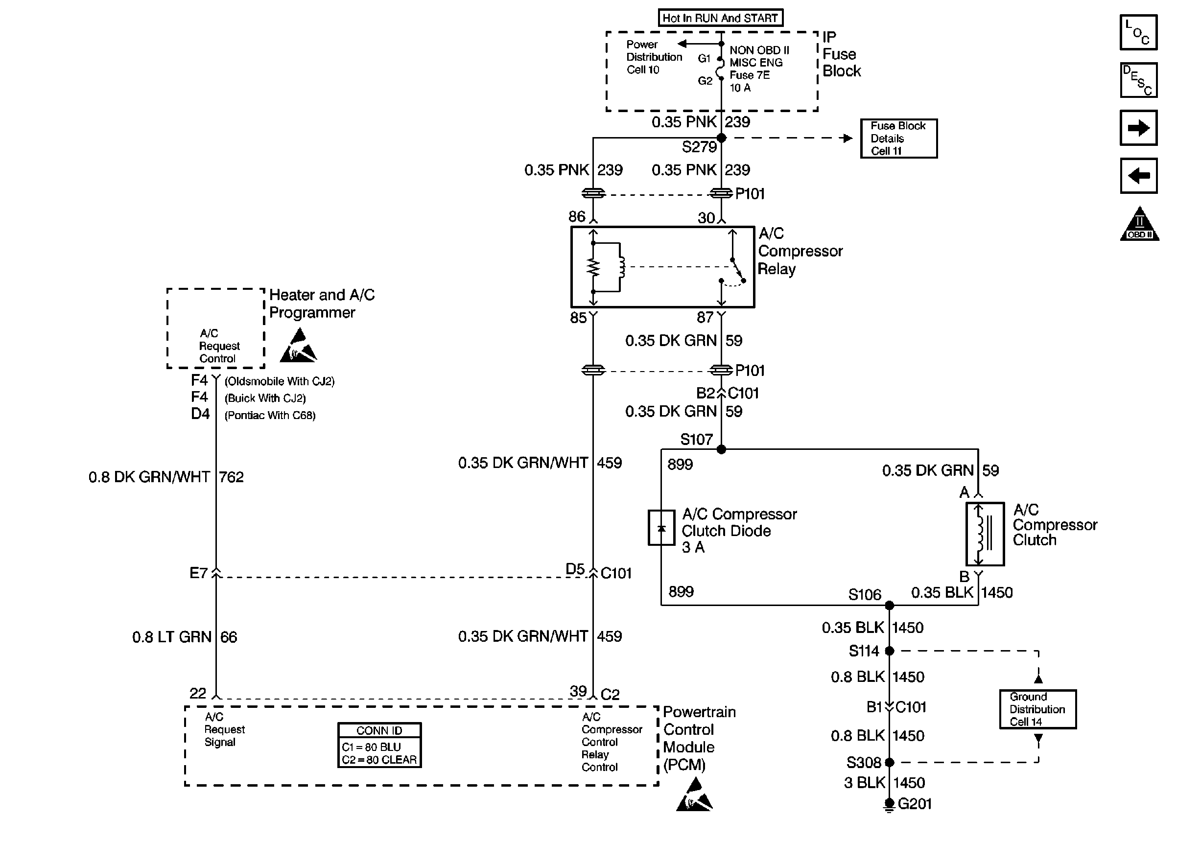
| Figure 17: |
Cell 20: HVAC Programmer
|
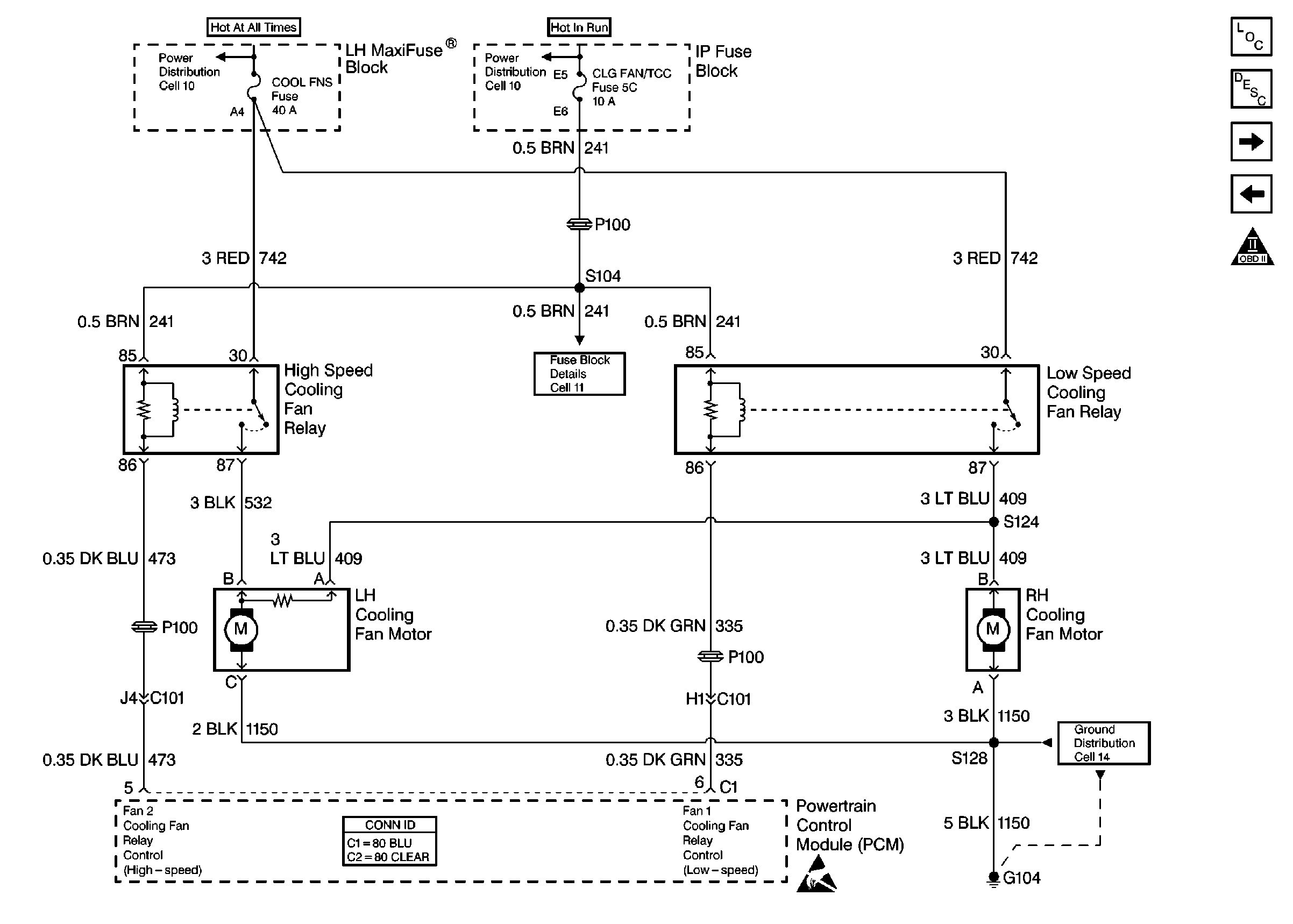
| Figure 18: |
Cell 20: Cooling Fans
|
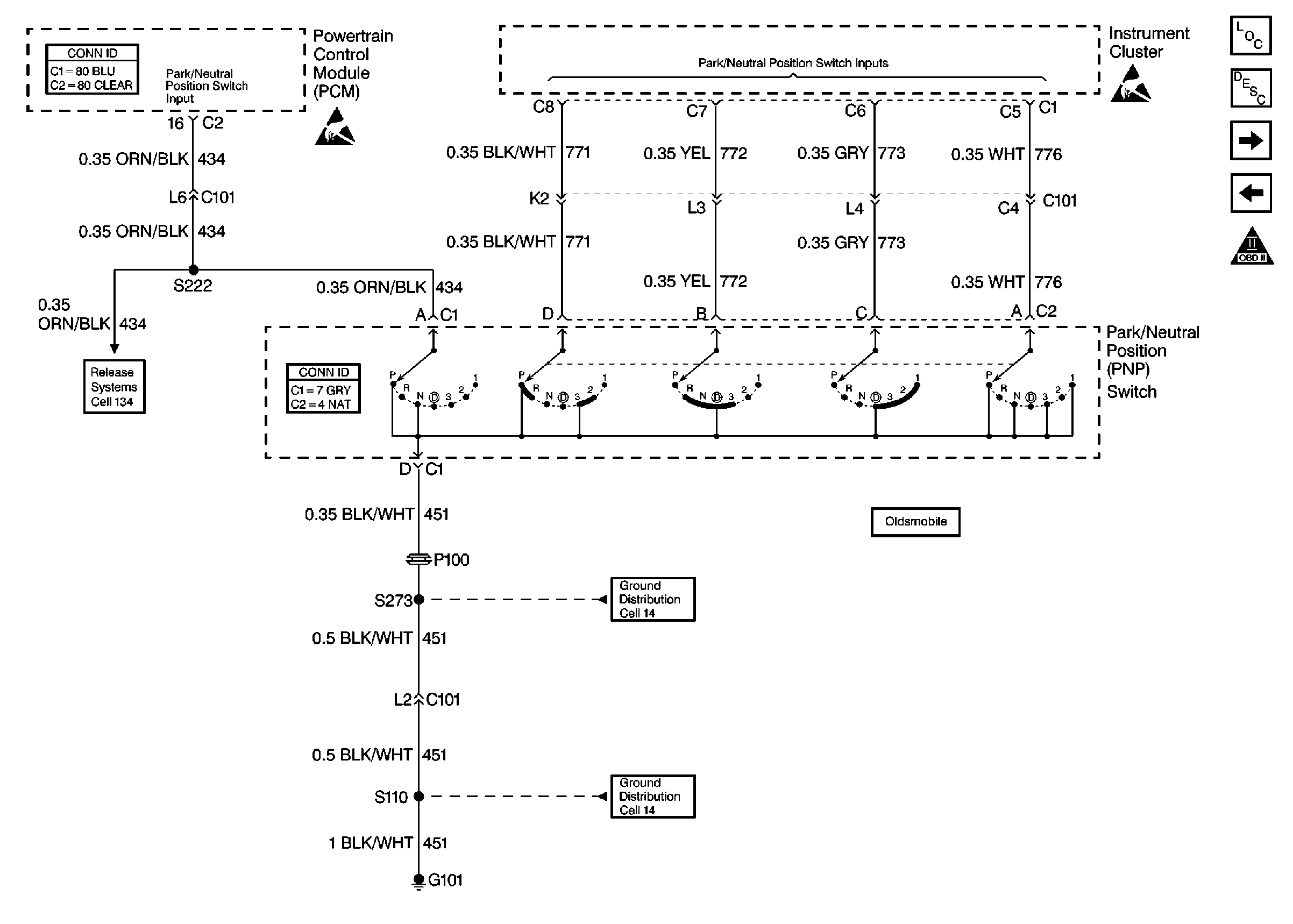
| Figure 19: |
Cell 20: PNP Switch (Trans Range)
|
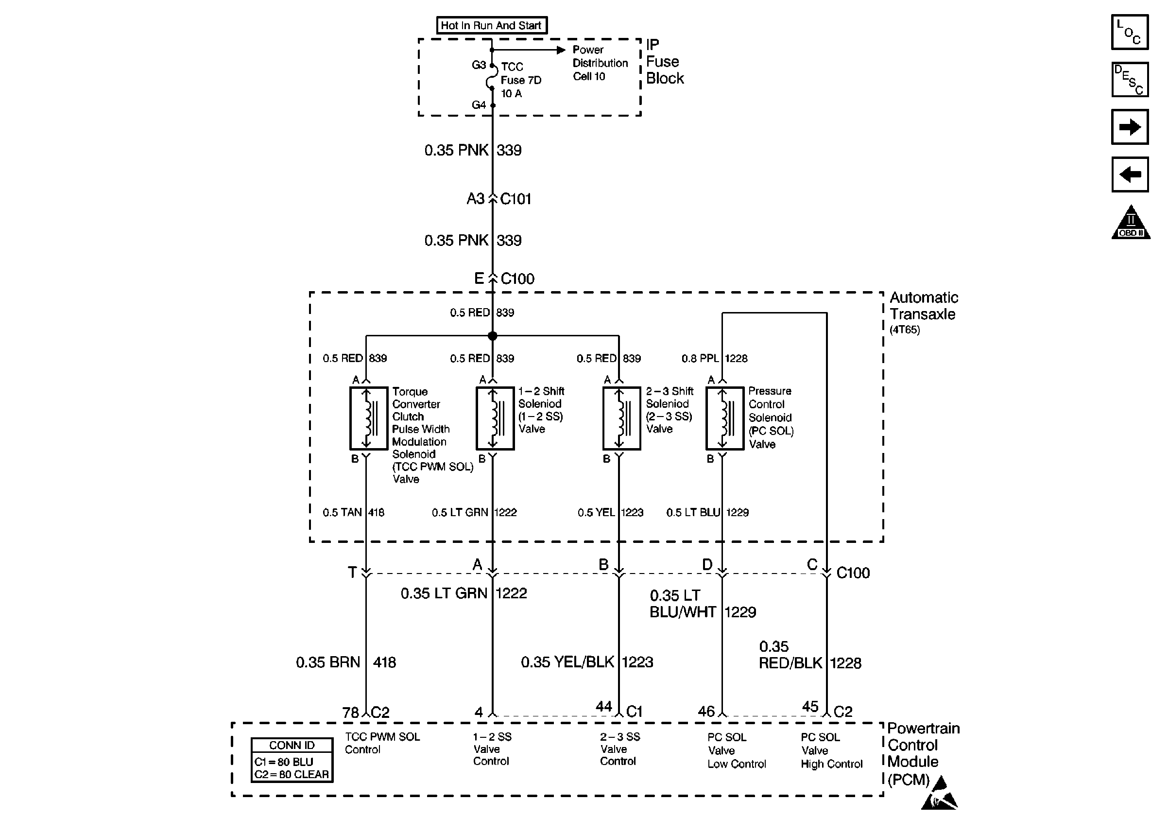
| Figure 20: |
Cell 20: Transaxle -- Solenoids
|
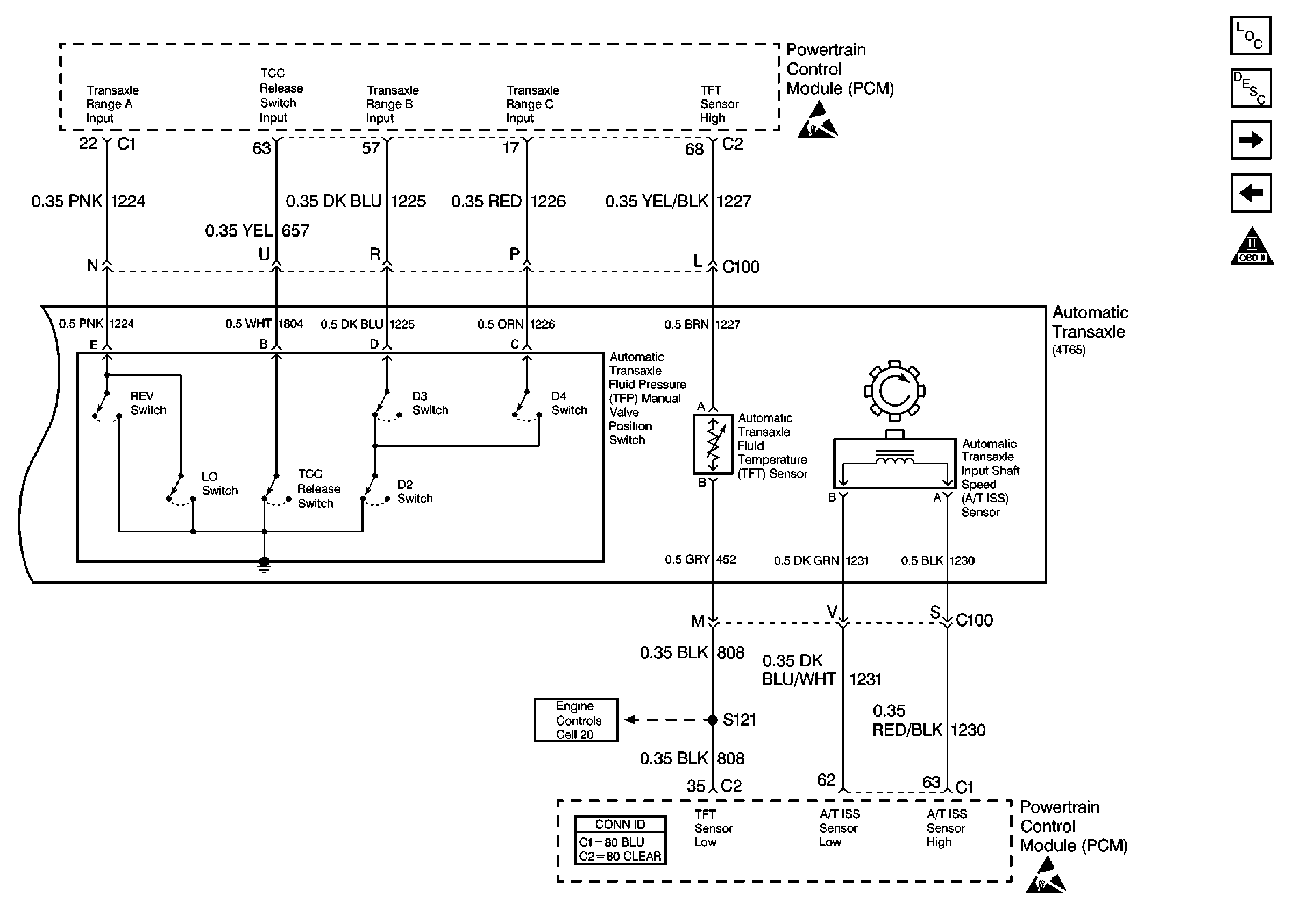
| Figure 21: |
Cell 20: Transaxle -- Sensors and TR Switch
|
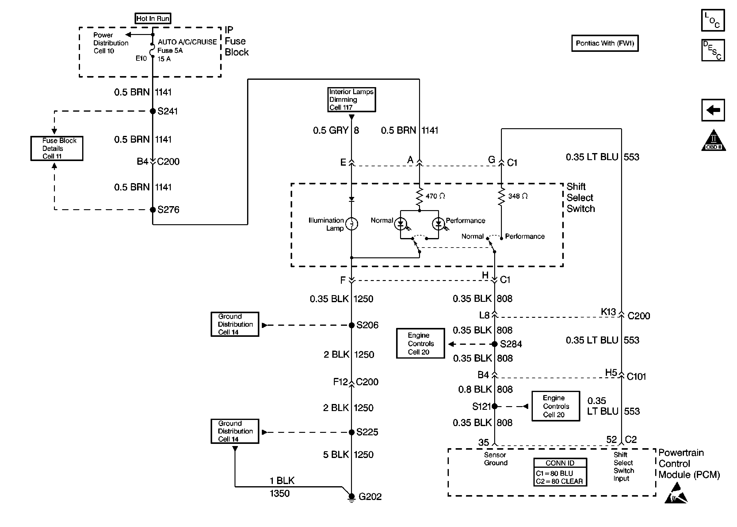
| Figure 22: |
Cell 20: Shift Select Switch
|


