Removal Procedure
Tools Required
| • | J 2619-01 Slide Hammer |
| • | J 28733-B Front Hub Spindle Remover |
| • | J 33008 Axle Shaft Remover |
| • | J 36226 Ball Joint Separator |
- Raise the vehicle and suitably support. Refer to Lifting and Jacking the Vehicle in General Information.
- Remove the wheel and tire. Refer to Wheel Removal in Wheel and Tires.
- Loosen or remove the stabilizer shaft link assembly bolt as needed. Refer to Stabilizer Shaft Replacement in Steering.
- Remove the ball joint cotter pin and nut.
- Loosen the joint using the J 36226 . The grease fitting may have to be removed from the ball joint for tool access. If removing the right axle, turn the wheel to the left; if removing the left axle, turn the wheel to the right.
- With the pry bar between the suspension support and the lower control arm, separate the joint.
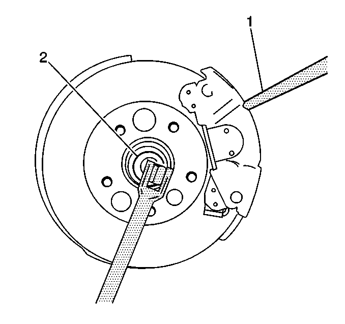
- Remove the hub nut (2). Insert a drift or screwdriver (1) into the caliper and rotor to prevent the rotor from turning.
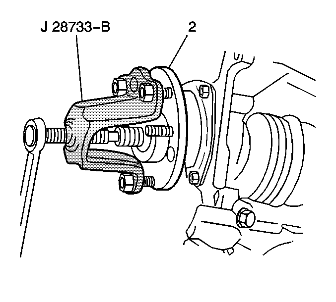
- Disconnect the axle from the hub using the (1) J 28733-B . The hub may be partially installed to protect the threads. Move the strut and knuckle rearward.
- Using the (4) J 33008 and the (2) J 2619-01 , disconnect the drive axle from the transaxle.
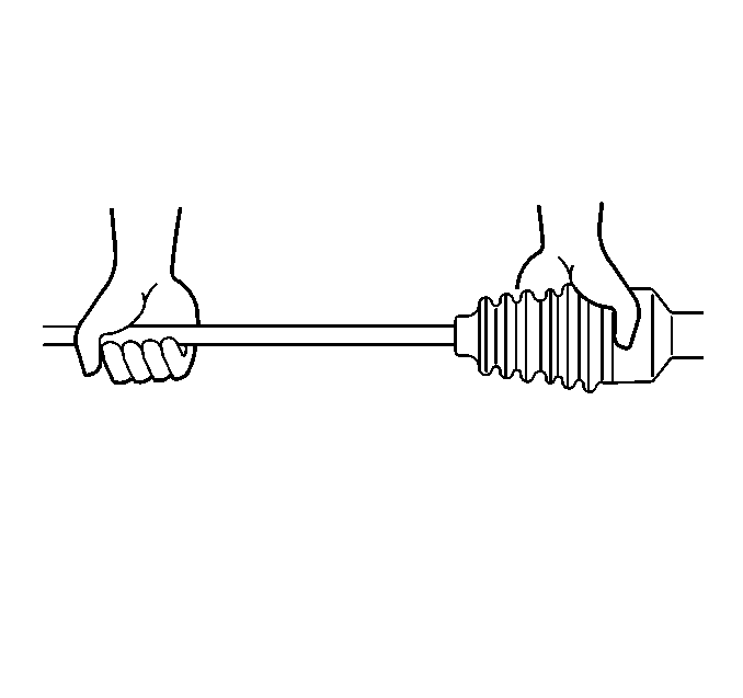
Notice: Do not attempt to free the ball stud by using a pickle fork or wedge type tool, because seal or bushing damage could result. Use the proper tool to separate all ball joints.
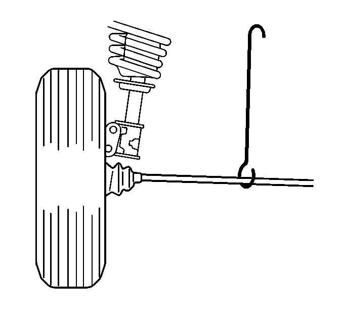
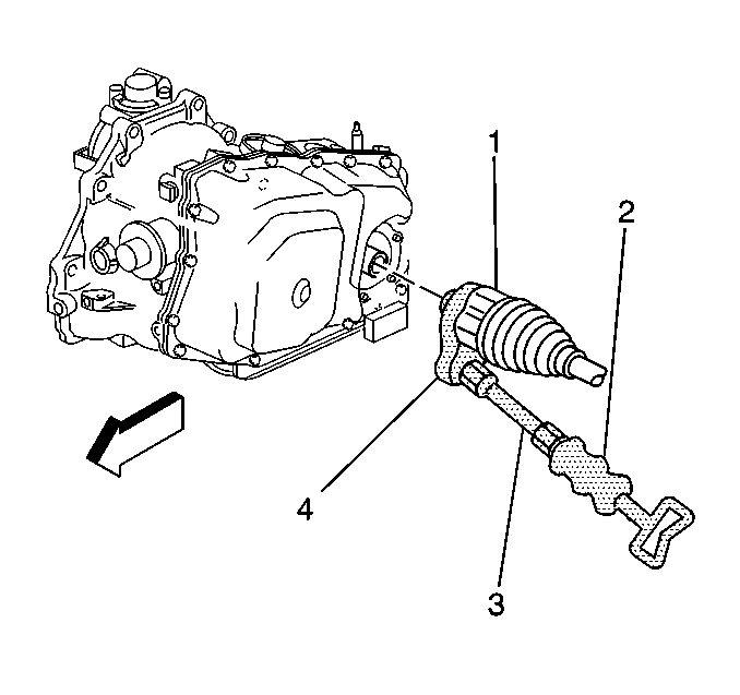
Notice: Do not overextend the wheel drive shaft. Allowing the inboard joint to overextend can cause separation of the internal components and lead to joint failure.
Installation Procedure
- Inspect the tripot housing at the transmission seal surface for corrosion, if corrosion is present, sand the surface in a rotational motion around the sealing surface with 320 grit emery cloth until smooth.
- Lubricate the tripot housing surface with clean transmission fluid.
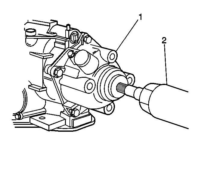
- Push the axle into the transaxle (1). Verify that the drive axle is seated by grasping the inner joint housing and pulling. Do not pull on the drive axle shaft.
- Install the drive axle into the hub and bearing. Install a new hub nut (2). Insert a drift or screwdriver (1) into the caliper and rotor to prevent the rotor from turning.
- Connect the ball joint to the knuckle.
- Install the cotter pin. In order to align the slot in the nut, tighten nut (up to one more flat).
- Install the stabilizer shaft link assembly. Tighten nut to 17 N·m (13 lb ft). Refer to Stabilizer Shaft Replacement in Steering.
- Install the wheel and tire. Refer to Wheel Installation in Wheel and Tires.
- Lower the vehicle.

Notice: Use the correct fastener in the correct location. Replacement fasteners must be the correct part number for that application. Fasteners requiring replacement or fasteners requiring the use of thread locking compound or sealant are identified in the service procedure. Do not use paints, lubricants, or corrosion inhibitors on fasteners or fastener joint surfaces unless specified. These coatings affect fastener torque and joint clamping force and may damage the fastener. Use the correct tightening sequence and specifications when installing fasteners in order to avoid damage to parts and systems.
Tighten
Hub nut to 145 N·m (107 lb ft).
Tighten
Ball joint nut to 10 N·m (88 lb in). Then
tighten an additional 120 degrees (2 flats on nut) during which a torque of
55 N·m (41 lb ft) must be obtained.
