GM Service Manual Online
For 1990-2009 cars only

The front and rear bumper assemblies consist of the following parts:

    • The impact bar
    • The hydraulic energy absorbers
    • The polyurethane fascia

The impact bar bolts to the energy absorbers. The energy absorbers mount inside the lower rails. The energy absorbers bolt at the front and rear locations. The fascia attaches to the following locations:

    • The fenders
    • The impact bar
    • At the wheel openings

The bumpers are designed so that the vehicle can withstand a collision into a fixed barrier at 8 km/h (5 mph) with only limited damage. After absorbing the energy of the collision, the energy absorbers restore the bumper to its original position. If the absorber does not return to its original position, replace the absorber. Inspect the absorber only after you have removed all of the damaged components.

The energy absorber consists of 2 main sub-assemblies:

    • The cylinder tube assembly
    • The piston tube assembly

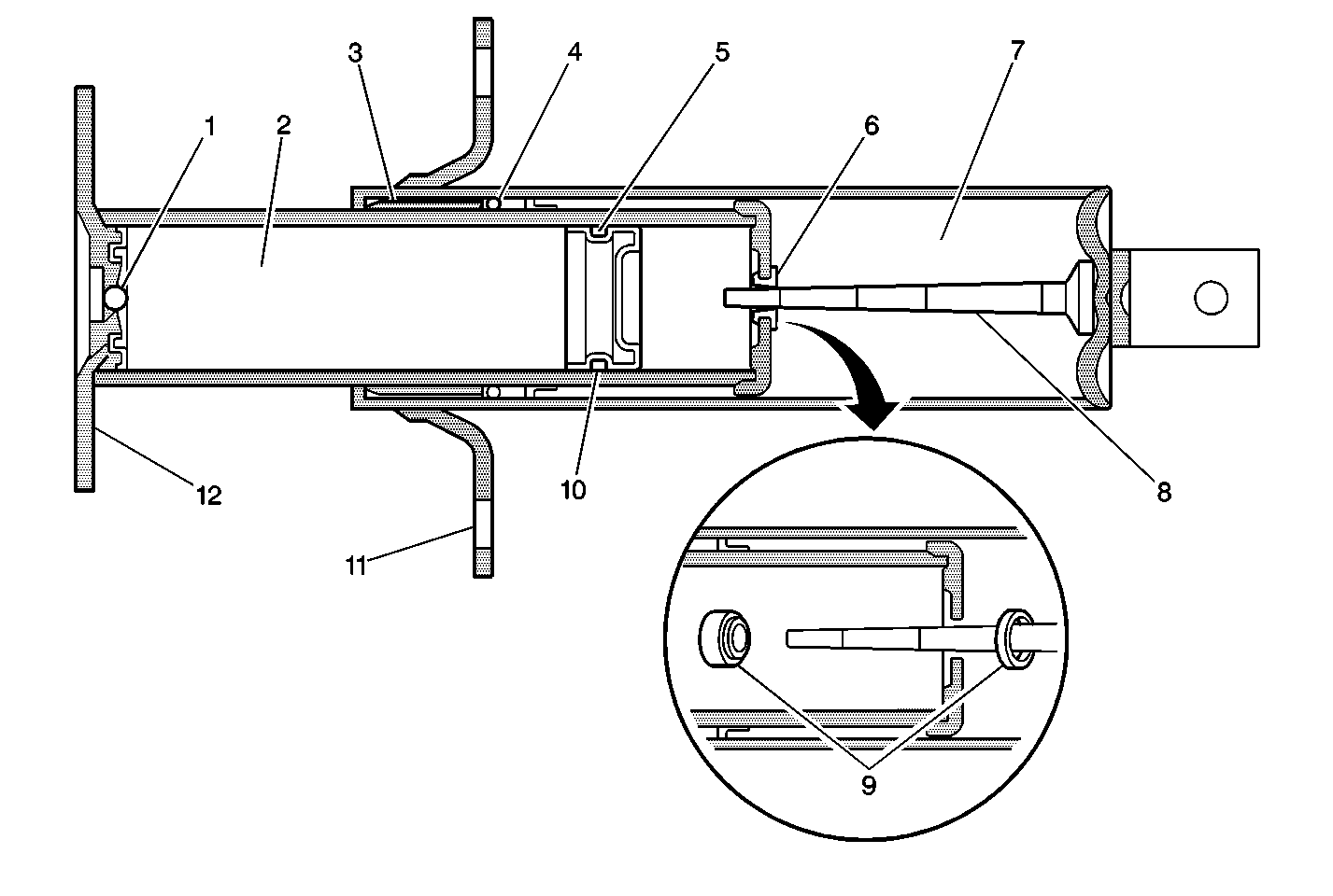
Two-Stage Energy Absorber


Object Number: 312217  Size: MF
(1)Sealing Ball
(2)Gas-Filled Piston Tube
(3)Stop Ring
(4)Seal
(5)Floating Piston
(6)Orifice
(7)Cylinder Tube filled with Hydraulic Fluid
(8)Metering Pin
(9)Orifice after High-Speed Impact
(10)Piston Seal
(11)Frame Bracket
(12)Bumper Bracket

The cylinder tube assembly is filled with a hydraulic fluid. The cylinder tube consists of the following components:

    • A frame bracket
    • A cylinder tube
    • A rear mounting bracket
    • A metering pin

The piston tube assembly is filled with an inert gas under pressure. The piston tube consists of the following components:

    • A bumper bracket
    • A piston tube
    • A piston
    • A piston seal
    • A stop-ring
    • A stop-ring seal
    • A breakaway orifice

The orifice replaces the calibrated orifice that is used in conventional single stage energy absorbers. This plug provides the two state action.

In vehicle impacts below 8 km/h (5 mph), the two-stage energy absorber acts as a conventional single stage energy absorber. As the energy absorber is collapsed, the hydraulic fluid in the cylinder tube is forced into the piston tube through an orifice in the brass blowout plug. The metering pin controls the rate at which the hydraulic fluid passes through the brass plug into the piston tube. The controlled movement of hydraulic fluid provides the energy absorbing action.

In vehicle impacts from 8 km/h (5 mph) to 48.2 km/h (30 mph), the brass plug is designed to blow off its seat, providing the second stage action. With the brass plug dislodged, the passageway for hydraulic fluid becomes greatly enlarged. The large opening allows the fluid to move rapidly from the cylinder tube to the piston tube. This provides energy absorption at greater impulses. Due to the one-time (non-repeatable) nature of the two-stage action, at these speeds you must examine the energy absorber after a collision in order to verify the two-stage operation.

After a high-speed impact, you must replace the unit.

In either stage of absorber action, the hydraulic fluid that is forced from the cylinder tube into the piston tube displaces the floating piston and compresses the inert gas behind the piston. After impact, the pressure of the compressed gas behind the floating piston forces the hydraulic fluid back into the cylinder tube assembly. This extends the energy absorber to the normal position.