Manifold Absolute Pressure Sensor Replacement VIN K
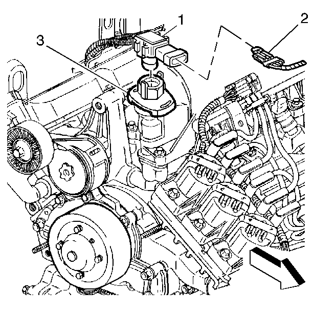
On VIN K applications, the manifold absolute pressure (MAP) sensor is mounted on the PCV valve cover.
Removal Procedure
- Turn OFF the ignition.
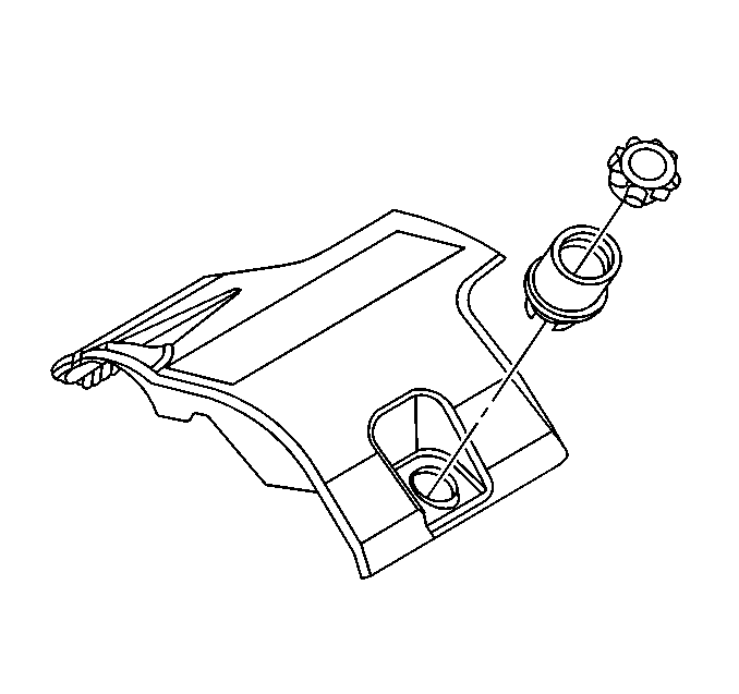
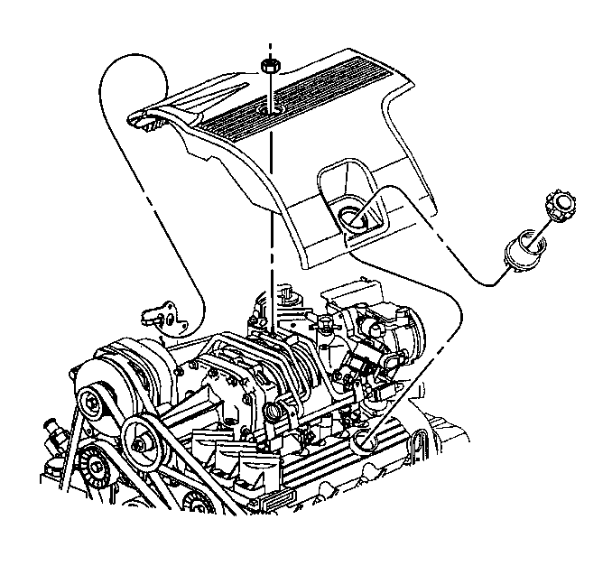
- Remove the fuel injector sight shield. Refer to Fuel Injector Sight Shield Replacement in Engine Mechanical.
- Disconnect the electrical connector (2) from the MAP sensor (1).
- Carefully bend the locking tabs retaining the MAP sensor (1) to the PCV valve cover (3) enough to remove the MAP sensor. Pull the sensor straight out of the PCV valve cover.


Installation Procedure
- Ensure that the seal is installed on the MAP sensor and that the seal is not damaged.
- Position and install the MAP sensor (1) to the PCV valve cover (3). Ensure that the locking tabs engage to hold the MAP sensor to the PCV valve cover.
- Connect the MAP sensor electrical connector to the MAP sensor (1).
- Install the fuel injector sight shield. Refer to Fuel Injector Sight Shield Replacement in Engine Mechanical.


Manifold Absolute Pressure Sensor Replacement VIN 1
Removal Procedure
- Turn OFF the ignition.
- Remove the fuel injector sight shield. Refer to Fuel Injector Sight Shield Replacement in Engine Mechanical.
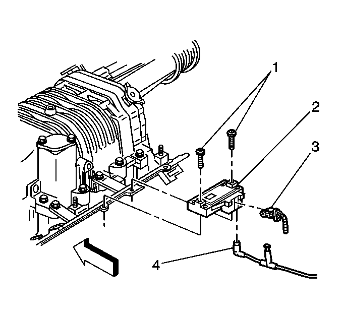
- Remove the 2 bolts (1) from the manifold absolute pressure (MAP) sensor (2).
- Disconnect the electrical connector (3) from the MAP sensor (2).
- Disconnect the vacuum hose (4) from the MAP sensor.
- Remove the MAP sensor from the engine.


Installation Procedure
- Connect the electrical connector (3) to the MAP sensor (2).
- Connect the vacuum hose (4) to the MAP sensor.
- Position the MAP sensor to the bracket and secure the sensor with the bolts (1).
- Install the fuel injector sight shield. Refer to Fuel Injector Sight Shield Replacement in Engine Mechanical.

Notice: Use the correct fastener in the correct location. Replacement fasteners must be the correct part number for that application. Fasteners requiring replacement or fasteners requiring the use of thread locking compound or sealant are identified in the service procedure. Do not use paints, lubricants, or corrosion inhibitors on fasteners or fastener joint surfaces unless specified. These coatings affect fastener torque and joint clamping force and may damage the fastener. Use the correct tightening sequence and specifications when installing fasteners in order to avoid damage to parts and systems.
Tighten
Tighten the bolts to 3 N·m (27 lb in)

