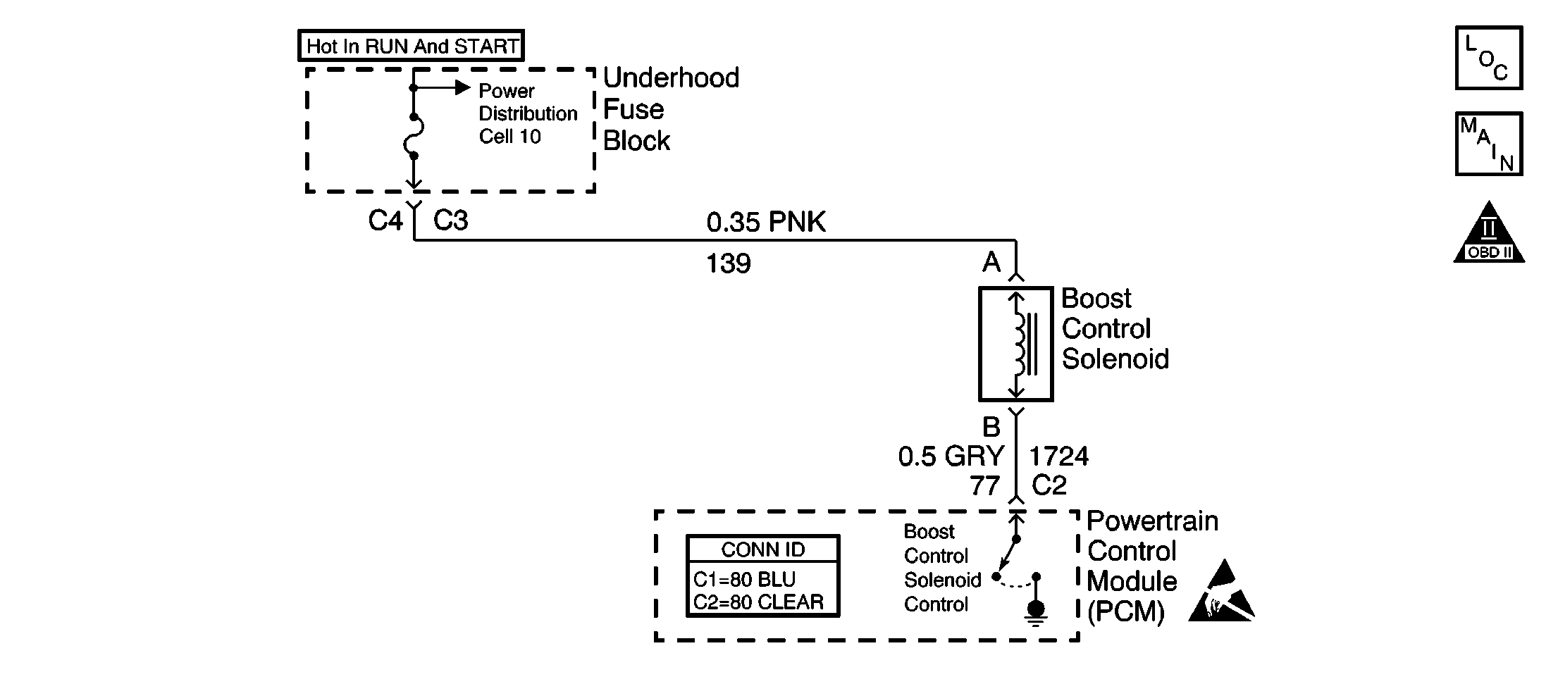
Circuit Description
Under most conditions, the PCM commands the boost control solenoid to operate at a 100 percent duty cycle (ON) to allow full boost pressure upon demand. However, if reverse gear is selected or the PCM detects rapid deceleration or engine load is extremely high, reduced boost pressure is desired. Under these conditions, the PCM commands the boost control solenoid to operate at a 0 percent duty cycle (OFF), which opens the bypass valve. With the Bypass valve open, boost pressure is reduced by recirculating intake air back through the supercharger inlet.
Diagnostic Aids
If the Boost Control System Check has been performed and no electrical or vacuum related fault is found, check for the following conditions:
| • | A misadjusted or sticking bypass valve actuator. Refer to Supercharger Bypass Valve Actuator Replacement . |
| • | Any binding in the bypass valve or the bypass valve linkage. Refer to Boost Control System Description . |
An intermittent may be caused by a faulty connection, rubbed through wire insulation, or a wire broken inside the insulation. Check for the following conditions:
| • | Inspect the PCM harness connector for backed out terminals, improper mating, improperly formed or damaged terminals, faulty terminal-to-wire connections, and a damaged harness. Use a corresponding mating terminal to test for proper terminal tension. |
| • | Test for intermittents. Disconnect the PCM and use a DMM to monitor the voltage between the control circuit of the boost control solenoid at the PCM connector and ground. With the key on, observe the voltage while manipulating the related connectors and the wiring harness. If the failure is induced, the voltage display will change. This may indicate the location of the fault. |
Test Description
The numbers below refer to the step numbers on the diagnostic table.
-
Verifies ignition feed to the boost control solenoid.
-
The boost control solenoid should be commanded off with the ignition on and the engine not running. If the system is functioning properly, the test lamp should be off.
-
Ensures that the PCM can control the ODM output for the boost control solenoid, and that the control circuit of the boost control solenoid is not open.
-
Checks for a malfunctioning boost control solenoid.
-
This vehicle is equipped with a PCM which utilizes an electrically erasable programmable read-only memory (EEPROM). If the PCM is replaced, the new PCM must be programmed.
Step | Action | Values | Yes | No |
|---|---|---|---|---|
1 | Was the Powertrain On-Board Diagnostic (OBD) System Check performed? | -- | ||
Does the test lamp illuminate? | -- | |||
Connect the test lamp between the harness connector terminals of the boost control solenoid . Does the test lamp illuminate? | -- | |||
Does the test lamp illuminate when the solenoid output is commanded on? | -- | |||
Does the vacuum approximately equal the specified value? | 0 in. Hg | |||
6 |
Is the vacuum more than than the specified value with the solenoid off? | 15 in. Hg | ||
7 |
Was a problem found? | -- | ||
8 |
Is the vacuum more than the specified value? | 15 in. Hg | Go to Diagnostic Aids | |
9 | Repair the restriction in the inlet vacuum signal hose to the bypass valve actuator or the blocked inlet vacuum source. Did you complete the repair? | -- | -- | |
10 |
Was a problem found? | -- | ||
11 | Check the fuse for the ignition feed circuit of the boost control solenoid. Is the fuse open? | -- | ||
12 | Locate and repair a short to ground in the ignition feed circuit. Refer to Wiring Repairs in Wiring Systems. Did you complete the repair? | -- | -- | |
13 | Locate and repair an open in the ignition feed circuit to the boost control solenoid. Refer to Wiring Repairs in Wiring Systems. Did you complete the repair? | -- | -- | |
14 |
Does the test lamp illuminate? | -- | ||
15 | Locate and repair a short to ground in the control circuit of the boost control solenoid . Refer to Wiring Repairs in Wiring Systems. Is the action complete? | -- | -- | |
16 |
Was a problem found? | -- | ||
17 |
Was a problem found? | -- | ||
18 | Replace the boost control solenoid. Refer to Boost Control Solenoid Replacement . Did you complete the repair? | -- | -- | |
19 |
Was a problem found? | -- | ||
|
Important: The replacement PCM must be programmed. Refer to Powertrain Control Module Replacement/Programming . Replace the PCM. Did you complete the repair? | -- | -- | ||
21 |
Does the MAP decrease when the boost solenoid is commanded on, and increase when the Boost Sol. is commanded off? | -- | ||
22 | Reconnect the inlet vacuum signal line to the bypass valve actuator. Is the action complete? | -- | System OK | -- |
