Info - Door Trim Repair Procedure

| Subject: | Door Trim Repair Procedure |
| Models: | 2000 Buick LeSabre |
| 2000 Pontiac Bonneville |
This bulletin is being revised to update the model and repair information. Please discard Corporate Bulletin Number 99-08-110-007 (08-Body and Accessories).
During door panel removal, heat stakes holding the metal bracket on the backside of the trim panel may break.
Repair Procedure
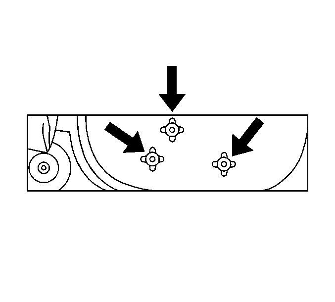
Figure 1

- In the center of the three retaining nubs (on the back of the trim panel), drill a 3.175 mm (1/8 in) hole, 19 mm (¾ in) deep in all three nubs (use a drill stop).
- Install the bracket on the trim pad.
- Install the three screws (P/N 11509428). See Figure 1 for location.
- If epoxy was used, complete steps 3 and 4 and allow the trim pad to set for one hour before installation.
In some cases, the retaining nub holes may have a larger hole than the above drill size. In this case, apply 3M™ Automix™ Fast Cure Epoxy Adhesive or GM Compoxy Repair Compound (P/N 12377980), or equivalent, to the three holes and proceed to the next step.
Door Trim Panel R&R
Notice: To avoid future door panel damage, the following procedure should be used.
- Remove the inside door handle bezel and the electrical connector.
- Remove the door speaker bezel at the top of the door, using J 38778. The bezel is attached with one push-in retainer.
- Remove the fastener in the trim panel at the bottom rear corner of the door or behind the reflector at the rear of the door.
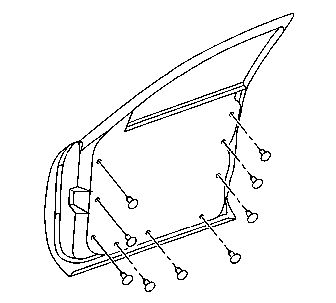
- Insert J 38778 between the door and the lower edge of the door trim panel. Center the trim panel plastic pin in the groove of the tool and pop the pin from the door. See Figure 2 for location of the pins.
- After releasing the bottom edge, hold the panel away from the door about one inch to help disengage the front and the rear edge pins.
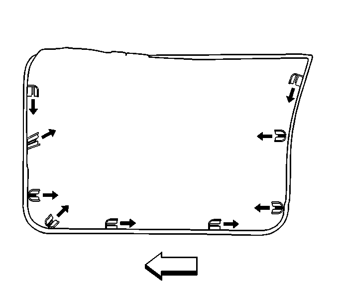
- After popping the pins, slide each from its cage and allow to fall from the door trim. See Figure 3 for the direction of the pin removal.
- To remove the trim panel, pull upward to release the electrical connector and set panel aside.
- Use needle nose pliers to depress the door mounted spring clip metal tabs. Slide the black plastic retainers from the spring clips.
- Insert the black plastic retainers into the trim panel metal retainer.
- Slide the push-pins in their cages, with the three long pins at the bottom of the trim panel.
- Connect the door wiring harness and the routing clip to the door module.
- Hold the top of the trim panel away from the top of the door about six inches and set the three lower push-pins in the door retainers. Push the top of the door trim panel toward the door.
- With all pins aligned, push the three lower pins to the door. This automatically aligns the metal clips to the plastic retainers.
- Push on the upper edge to engage the top rail over the window inner belt seal strip. Tap on the door panel at the remaining retainers.
- Push on the center of the armrest to make sure the center spring clips are seated. After seating the spring clips, pull on the armrest to make sure the clips are seated properly.
- Reinstall the speaker bezel.
- Retainer the door handle bezel.
- Reinstall the fastener behind the door reflector or at the bottom rear corner of the door.
Notice: Do not pull the door pad outboard more than one inch or breakage will occur.
Figure 2

Figure 3

Parts Information
Part Number | Description |
|---|---|
12377980 | Compoxy Repair Compound |
11509428 | Screw |
Parts are currently available from GMSPO.
Warranty Information
For vehicles repaired under warranty, use:
Labor Operation | Description | Labor Time |
|---|---|---|
C3348 | Trim Asm, Front Door (RH) - R&R or Replace | 0.2 hr |
C3358 | Trim Asm, Front Door (LH) - R&R or Replace | 0.2 hr |
Add: | To Drill Holes | 0.1 hr |
