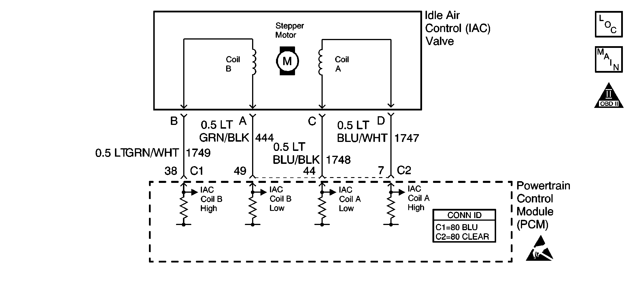
The PCM controls engine idle speed by adjusting the position of the
idle air control (IAC) motor pintle. The IAC is a bi-directional motor driven
by two coils. The PCM sends pulses (steps) to the IAC to extend or retract
the IAC pintle into a passage in the throttle body to decrease or increase
air flow. The commanded IAC position (displayed in counts) can be monitored
on the scan tool. A lower number of counts indicates less commanded airflow
(pintle extended). This method allows highly accurate control of idle speed
and quick response to changes in engine load. If the PCM detects a condition
where too high of an idle speed is present and the PCM is unable to adjust
idle speed by decreasing the IAC counts, DTC P0507 will set indicating a
problem with the idle control system.
Reviewing the Fail Records vehicle mileage since the diagnostic test
last failed may help determine how often the condition that caused the DTC
to be set occurs. This may assist in diagnosing the condition.
The numbers below refer to the step numbers on the diagnostic table.
DTC P0507 - Idle Air Control System RPM High
Step
| Action
| Values
| Yes
| No
|
1
| Was
the Powertrain On Board Diagnostic (OBD) System Check performed?
| --
|
Go to Step 2
| Go to
Powertrain On Board Diagnostic (OBD) System Check
|
2
| Are any other DTCs set?
| --
| Go to
Diagnostic Trouble Code (DTC) List/Type
|
Go to Step 3
|
3
|
- Start the engine.
- Turn OFF all accessories (A/C, rear defroster etc.).
- Using a scan tool, command the RPM up to 1500, down to 650, and
then up to 1500 while monitoring Engine Speed on the scan tool.
Does the engine speed vary less than the specified value from each
RPM command?
| 100 RPM
| Go to Diagnostic Aids
|
Go to Step 4
|
4
|
- Disconnect the idle air control (IAC) valve.
- Install a J 37027-A
IAC system monitor.
- With the engine running, command the RPM up to 1500, down to 650,
and then up to 1500 while observing the node light.
Does each node light cycle red and green (never OFF)?
| --
|
Go to Step 6
|
Go to Step
5
|
5
|
- Check the following circuits for an open, a short to voltage,
or a short to ground:
- If a problem is found, repair as necessary. Refer to
Wiring Repairs
in Wiring Systems .
Was a problem found?
| --
|
Go to Step 11
|
Go to Step 9
|
6
|
- Check for a faulty connection at the IAC harness connector.
- If a problem is found, replace the terminals as necessary. Refer
to
Testing for Intermittent Conditions and Poor Connections
in Wiring Systems .
Was a problem found?
| --
|
Go to Step 11
|
Go to Step 7
|
7
|
- Visually/physically inspect for the following conditions:
| • | Any throttle body tampering (throttle lever stop screw turned) |
| • | A binding throttle plate or throttle shaft |
- If a problem is found, repair as necessary.
Was a problem found?
| --
|
Go to Step 11
|
Go to Step 8
|
8
| Replace the IAC valve. Refer to
Idle Air Control Valve Replacement
.
Did you complete the repair?
| --
|
Go to Step 11
| --
|
9
|
- Check for a faulty connection at the PCM harness connector.
- If a problem is found, replace any terminals as necessary. Refer
to
Testing for Intermittent Conditions and Poor Connections
in Wiring Systems .
Was a problem found?
| --
|
Go to Step 11
|
Go to Step 10
|
10
|
Important:: The replacement PCM must be programmed.
Replace the PCM. Refer to
Powertrain Control Module Replacement/Programming
.
Did you complete the repair?
| --
|
Go to Step 11
| --
|
11
|
- Start the engine.
- Turn OFF all accessories (A/C, rear defroster etc.).
- Using a scan tool, command the RPM up to 1500, down to 650, and
then up to 1500 while monitoring Engine Speed on the scan tool.
Does the engine speed vary less than the specified value from each RPM
command?
| 100 RPM
| System OK
|
Go to Step 2
|

