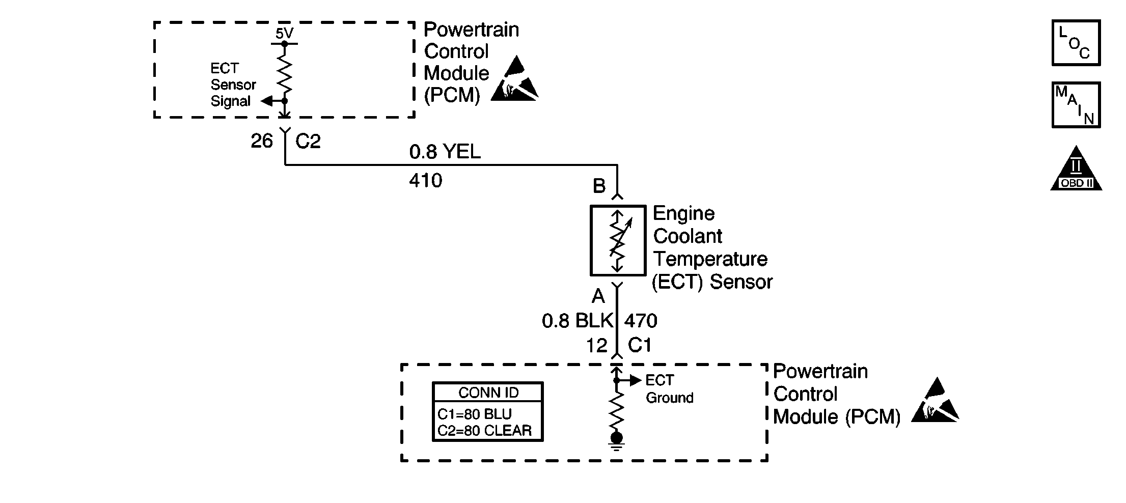
Circuit Description
The engine coolant temperature (ECT) sensor is a thermistor mounted in the engine coolant stream. The PCM applies a voltage (about 5.0 volts) through a pull up resistor to the ECT signal circuit. When the engine coolant is cold, the sensor (thermistor) resistance is high, therefore the PCM will measure a high signal voltage. As the engine coolant warms, the sensor resistance becomes less, and the ECT signal voltage measured at the PCM drops. With a fully warmed up engine, the ECT signal voltage should measure about 1.5 to 2.0 volts. If the PCM detects an ECT signal that is intermittently below the range of the ECT sensor, DTC P1114 will set.
Conditions for Running the DTC
The engine has been running for longer than 15 seconds.
Conditions for Setting the DTC
The ECT sensor intermittently indicates an engine coolant temperature of less than 114°C (237°F).
Action Taken When the DTC Sets
The PCM stores conditions which were present when the DTC set as Failure Records only. This information will not be stored as Freeze Frame Records.
Conditions for Clearing the MIL/DTC
| • | The DTC becomes history when the conditions for setting the DTC are no longer present. |
| • | The history DTC clears after 40 malfunction free warm-up cycles. |
| • | The PCM receives a clear code command from the scan tool. |
Diagnostic Aids
Check for the following conditions:
| • | A faulty connection at the PCM--Inspect the harness connectors for backed out terminals, improper mating, broken locks, improperly formed or damaged terminals, and faulty terminal to wire connections. Use a corresponding mating terminal to test for proper terminal tension. |
| • | Inspect the wiring harness for damage. If the harness appears to be OK, observe the ECT display on the scan tool while moving the connectors and wiring harnesses related to the ECT sensor. A change in the ECT display will indicate the location of the malfunction. |
| • | A skewed or mis-scaled ECT sensor, refer to Temperature Versus Resistance . |
Reviewing the Failure Records vehicle mileage since the diagnostic test last failed may help determine how often the condition that caused the DTC to be set occurs. This may assist in diagnosing the condition.
Step | Action | Values | Yes | No |
|---|---|---|---|---|
1 | Did you perform the Powertrain On Board Diagnostic (OBD) System Check? | -- | ||
2 | With a scan tool, select Diagnostic Trouble Codes (DTC). Does the scan tool indicate DTC P0117 also set? | -- | Go to DTC P0117 Engine Coolant Temperature (ECT) Sensor Circuit Low Voltage | |
3 | Test the signal circuit of the ECT sensor for an intermittent short to ground. Refer to Testing for Intermittent Conditions and Poor Connections and Wiring Repairs in Wiring Systems. Did you find and correct the condition? | -- | Go to Diagnostic Aids | |
4 |
Does the DTC reset? | -- | System OK |
