Tools Required
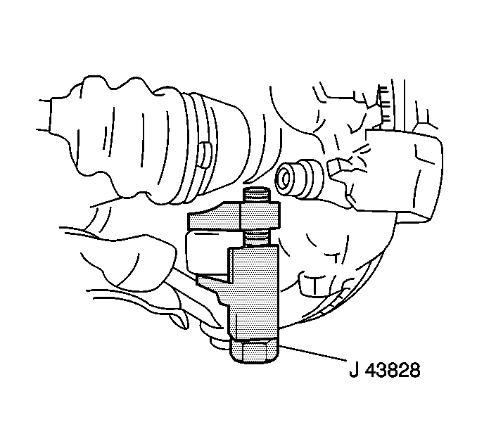
J 43828 Ball Joint Separator
Removal Procedure
- Raise and support the vehicle. Refer to Lifting and Jacking the Vehicle in General Information.
- Remove the tire and wheel. Refer to Tire and Wheel Removal and Installation in Tires and Wheels.
- Remove the stabilizer shaft link. Refer to Stabilizer Shaft Link Replacement .
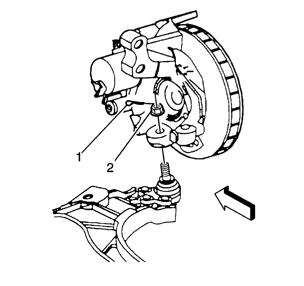
- Remove the cotter pin (1).
- Loosen the lower ball joint retaining nut (2) from the ball stud.
- Using J 43828 remove the lower ball joint from the steering knuckle.
- Remove the lower ball joint retaining nut.
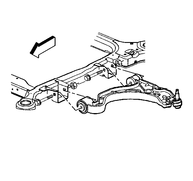
- Remove the lower control arm mounting bolts and nuts.
- Remove the lower control arm from the frame.
Notice: Use only the recommended tools for separating the ball joint from the knuckle. Failure to use the recommended tools may cause damage to the ball joint and seal.


Notice: Care must be exercised to prevent Tri-Pot joints from being over-extended. When either end of the shaft is disconnected, over-extension of the joint could result in separation of internal components and possible joint failure. Drive axle joint seal protectors should be used any time service is performed on or near the drive axles. Failure to observe this can result in interior joint or seal damage and possible joint failures.

Installation Procedure
- Install the lower control arm to the frame.
- Install the lower bolts, control arm and nuts.
- Install the lower ball joint and retaining nut to the steering knuckle.
- Continue to tighten the ball joint nut for cotter pin alignment and install the cotter pin.
- Install the stabilizer shaft link. Refer to Stabilizer Shaft Link Replacement .
- Install the tire and wheel. Refer to Tire and Wheel Removal and Installation in Tires and Wheels.
- Lower the vehicle.
- Inspect the trim height. Refer to Trim Height Specifications in Suspension General Diagnosis.
- Tighten the control arm bolts in the following sequence:
- Tighten the rear mounting bolt to 170 N·m (125 lb ft).
- Tighten the front mounting nut to 158 N·m (117 lb ft).

Important: Do not tighten the control arm nuts at this time. Before tightening the control arm mounting nuts, support the weight of the vehicle by the control arms in order to obtain the vehicle design trim heights.
Notice: Refer to Fastener Notice in the Preface section.
Tighten
Tighten the lower ball joint retaining nut to 10 N·m (89 lb in)
plus an additional 180 degrees.
Important: Do not exceed two slots during cotter pin alignment.
Tighten
