| Table 1: | Driver Information Center (DIC) Switch |
| Table 2: | Electronic Compass Module |
| Table 3: | Engine Oil Level Switch |
| Table 4: | Engine Oil Pressure (EOP) Sensor |
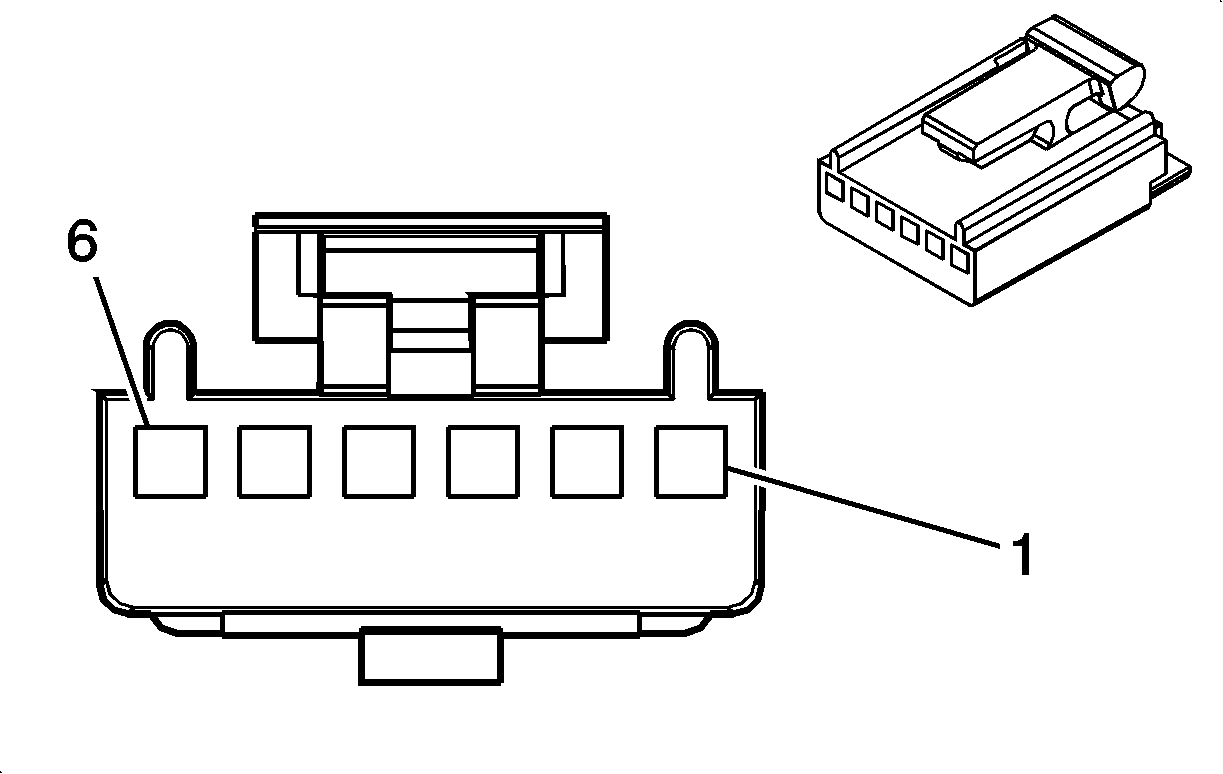
| Table 5: | Head Up Display (HUD) Switch |
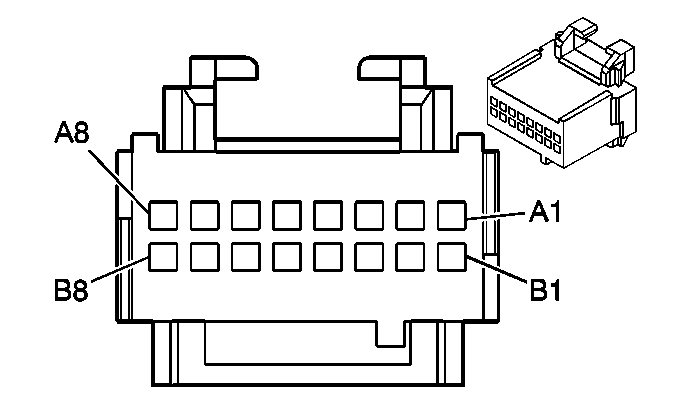
| Table 6: | Heads Up Display (HUD) |
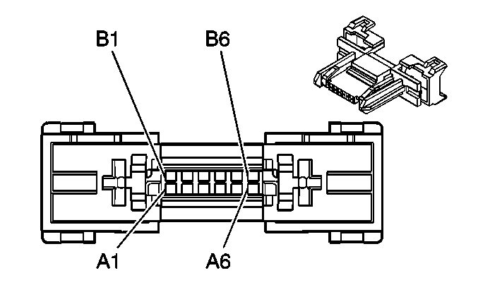
| Table 7: | Instrument Panel Cluster (IPC) C1 |
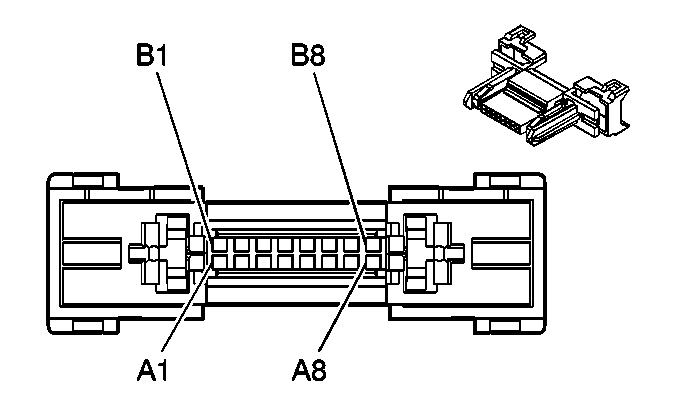
| Table 8: | Instrument Panel Cluster (IPC) C2 |
| Table 9: | Vehicle Speed Sensor (VSS) |
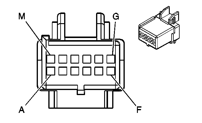
| |||||||
|---|---|---|---|---|---|---|---|
Connector Part Information |
| ||||||
Pin | Wire Color | Circuit No. | Function | ||||
A | YEL | 1491 | Backlight Lamps Control | ||||
B | LT BLU | 811 | Metric Conversion Switch Signal | ||||
C | LT GRN | 376 | Trip Odometer Reset Switch Signal | ||||
D | PNK | 893 | DIC Select Menu Switch Signal (W/U50/U2F) | ||||
E-H | -- | -- | Not Used | ||||
J | PNK/BLK | 1379 | DIC Reset Switch Signal (W/U50/U2F) | ||||
K | LT GRN | 1055 | Low Tire Pressure Reset Switch Signal | ||||
K | ORN | 1816 | DIC Mode Switch Signal (W/U50/U2F) | ||||
L | BLK | 450 | Ground | ||||
M | -- | -- | Not Used | ||||
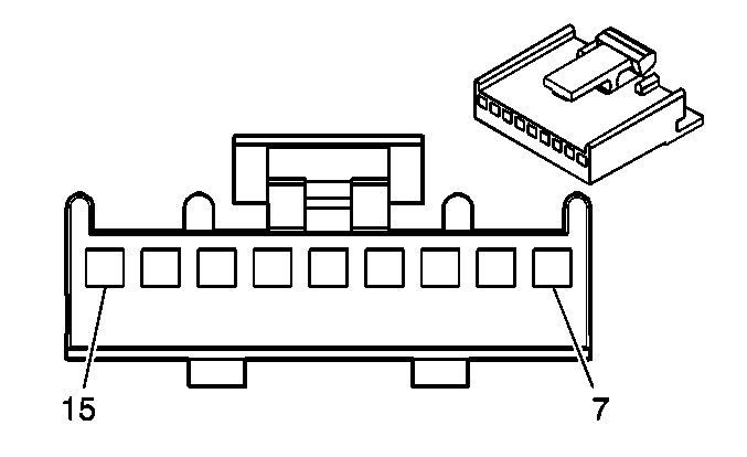
| |||||||
|---|---|---|---|---|---|---|---|
Connector Part Information |
| ||||||
Pin | Wire Color | Circuit No. | Function | ||||
7-8 | -- | -- | Not Used | ||||
9 | WHT | 193 | Rear Defog Relay Control | ||||
10 | -- | -- | Not Used | ||||
11 | PPL/WHT | 336 | Compass Data Signal | ||||
12 | TAN/WHT | 337 | Compass Clock Signal | ||||
13 | BRN | 41 | Ignition 3 Voltage | ||||
14 | BLK/WHT | 751 | Ground | ||||
15 | -- | -- | Not Used | ||||
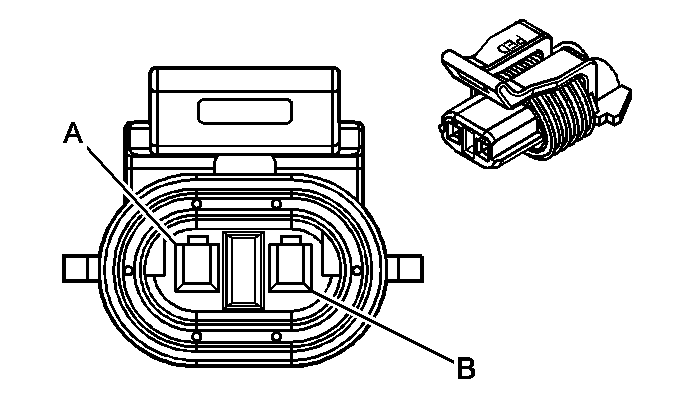
| |||||||
|---|---|---|---|---|---|---|---|
Connector Part Information |
| ||||||
Pin | Wire Color | Circuit No. | Function | ||||
A | BRN | 1174 | Oil Level Switch Signal | ||||
B | BLK/WHT | 1551 | Ground | ||||
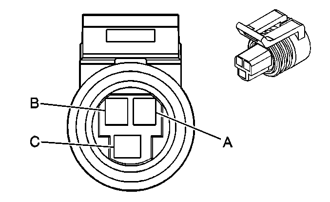
| |||||||
|---|---|---|---|---|---|---|---|
Connector Part Information |
| ||||||
Pin | Wire Color | Circuit No. | Function | ||||
A | BLK | 808 | Low Reference | ||||
B | GRY | 605 | 5 Volt Reference | ||||
C | TAN/WHT | 331 | Oil Pressure Sensor Signal | ||||
| |||||||
|---|---|---|---|---|---|---|---|
Connector Part Information |
| ||||||
Pin | Wire Color | Circuit No. | Function | ||||
1 | PPL/WHT | 724 | Vacuum Fluorescent (VF) Dimming Signal | ||||
2 | BLK | 450 | Ground | ||||
3 | YEL | 621 | HUD Image Down Control | ||||
4 | BRN | 622 | HUD Image Up Control | ||||
5 | BRN | 41 | Ignition 3 Voltage | ||||
6 | YEL | 1491 | Backlight Lamps Control | ||||
| |||||||
|---|---|---|---|---|---|---|---|
Connector Part Information |
| ||||||
Pin | Wire Color | Circuit No. | Function | ||||
A1 | BRN | 41 | Ignition 3 Voltage | ||||
A2 | ORN | 440 | Battery Positive Voltage | ||||
A3 | -- | -- | Not Used | ||||
A4 | BLK/WHT | 451 | Ground | ||||
A5 | -- | -- | Not Used | ||||
A6 | PPL | 1807 | Class 2 Serial Data | ||||
A7 | -- | -- | Not Used | ||||
A8 | DK GRN/ WHT | 817 | Vehicle Speed Signal | ||||
B1 | BRN | 622 | HUD Image Up Control | ||||
B2 | -- | -- | Not Used | ||||
B3 | YEL | 621 | HUD Image Down Control | ||||
B4 | -- | -- | Not Used | ||||
B5 | PPL/WHT | 724 | Vacuum Fluorescent (VF) Dimming Signal | ||||
B6 | -- | -- | Not Used | ||||
B7 | LT BLU | 14 | Left Turn Signal Lamps Supply Voltage | ||||
B8 | DK BLU | 15 | Right Turn Signal Lamps Supply Voltage | ||||
| |||||||
|---|---|---|---|---|---|---|---|
Connector Part Information |
| ||||||
Pin* | Wire Color | Circuit No. | Function | ||||
A1 | LT BLU | 14 | Left Turn Signal Lamps Supply Voltage | ||||
A2 | WHT | 2192 | Traction Ready Indicator Control (w/ NW9) | ||||
A2 | -- | -- | Not Used (w/o NW9) | ||||
A3 | DK BLU | 1537 | ABS Indicator Signal | ||||
A4 | WHT | 121 | Engine Speed Signal | ||||
A5 | PPL | 1807 | Class 2 Serial Data | ||||
A6 | PPL | 1807 | Class 2 Serial Data | ||||
B1 | BRN/WHT | 419 | MIL Control | ||||
B2 | TAN/WHT | 337 | Compass Clock Signal (w/ U50) | ||||
B2 | -- | -- | Not Used (w/o U50) | ||||
B3 | PPL | 333 | Brake Fluid Level Sensor Signal | ||||
B4 | DK GRN/ WHT | 817 | Vehicle Speed Sensor Signal | ||||
B5 | PNK | 893 | DIC Select Menu Switch Signal (w/ U50) | ||||
B5 | -- | -- | Not Used (w/o U50) | ||||
B6 | LT BLU | 1134 | Park Brake Switch Signal | ||||
Note: A Pins = Top of the Connector B Pins = Bottom of the Connector | |||||||
| |||||||
|---|---|---|---|---|---|---|---|
Connector Part Information |
| ||||||
Pin* | Wire Color | Circuit No. | Function | ||||
A1 | BLK/WHT | 99 | Windshield Washer Fluid Level Signal | ||||
A2 | BLK | 450 | Ground | ||||
A3 | -- | -- | Not Used | ||||
A4 | PPL | 2259 | Theft LED Signal | ||||
A5 | -- | -- | Not Used | ||||
A6 | PNK | 1039 | Ignition 1 Voltage | ||||
A7 | ORN | 440 | Battery Positive Voltage | ||||
A8 | BLK/WHT | 351 | Ground | ||||
B1 | -- | -- | Not Used | ||||
B2 | ORN | 1816 | DIC Mode Switch Signal (w/ U50) | ||||
B2 | -- | -- | Not Used (w/o U50) | ||||
B3 | PPL/WHT | 336 | Compass Data Signal (w/ U2F) | ||||
B3 | -- | -- | Not Used (w/o U2F) | ||||
B4 | LT GRN | 1055 | Low Tire Pressure Reset Switch Signal (w/o /U2F) | ||||
B4 | PNK/BLK | 1379 | DIC Reset Switch Signal (w/ U2F) | ||||
B5 | DK BLU | 15 | Right Turn Signal Lamps Supply Voltage | ||||
B6 | LT GRN | 376 | Trip Odometer Reset Switch Signal | ||||
B7 | LT BLU | 811 | Metric Conversion Switch Signal | ||||
B8 | YEL | 1491 | Backlight Lamps Control | ||||
Note: A Pins = Top of the Connector B Pins = Bottom of the Connector | |||||||
| |||||||
|---|---|---|---|---|---|---|---|
Connector Part Information |
| ||||||
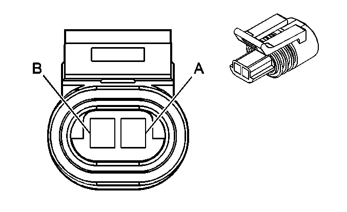
Pin | Wire Color | Circuit No. | Function | ||||
A | PPL | 401 | Signal Low - Front | ||||
B | YEL | 400 | Signal High - Front | ||||
