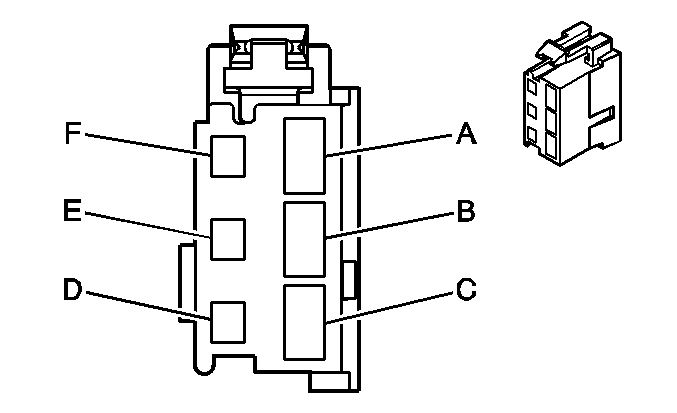
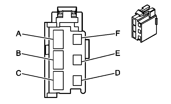
For 1990-2009 cars only
| Table 1: | Ignition Switch C1 |
| Table 2: | Ignition Switch C2 |

| |||||||
|---|---|---|---|---|---|---|---|
Connector Part Information |
| ||||||
Pin | Wire Color | Circuit No. | Function | ||||
A | ORN | 540 | Battery Positive Voltage | ||||
B | PNK | 3 | Ignition 1 Voltage | ||||
C | BRN | 4 | Accessory Voltage | ||||
D | -- | -- | Not Used | ||||
E | BLK/WHT | 451 | Ground | ||||
F | -- | -- | Not Used | ||||

| |||||||
|---|---|---|---|---|---|---|---|
Connector Part Information |
| ||||||
Pin | Wire Color | Circuit No. | Function | ||||
A | ORN | 540 | Battery Positive Voltage | ||||
ORN | 540 | Battery Positive Voltage | |||||
B | YEL | 5 | Crank Voltage | ||||
C | ORN | 300 | Ignition 3 Voltage | ||||
D | LT GRN | 80 | Key In Ignition Switch Signal | ||||
E | WHT | 1390 | Off/Run/Crank Voltage | ||||
F | -- | -- | Not Used | ||||
