Water Pump Replacement L36
Removal Procedure
- Drain the engine coolant. Refer to Cooling System Draining and Filling .
- Remove the drive belt. Refer to Drive Belt Replacement in Engine Mechanical - 3.8L.
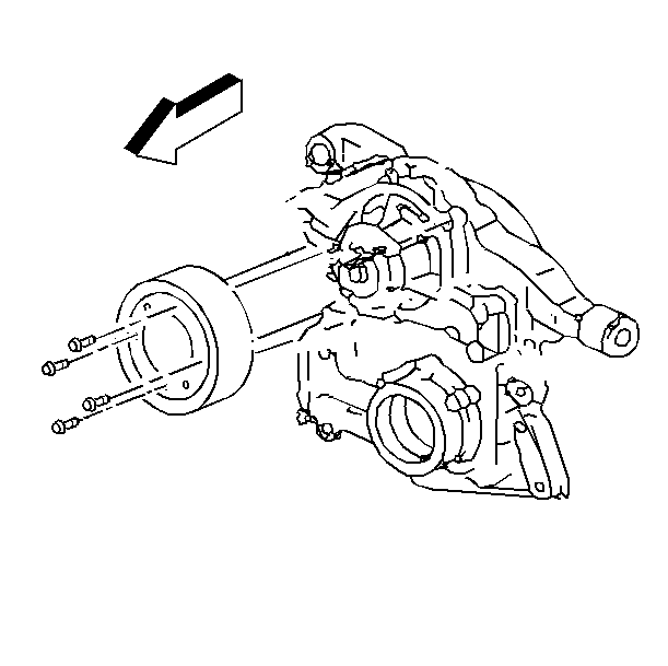
- Remove the water pump pulley bolts.
- Remove the water pump pulley.
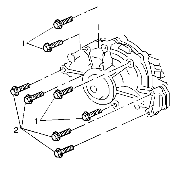
- Remove the water pump mounting bolts (1, 2).
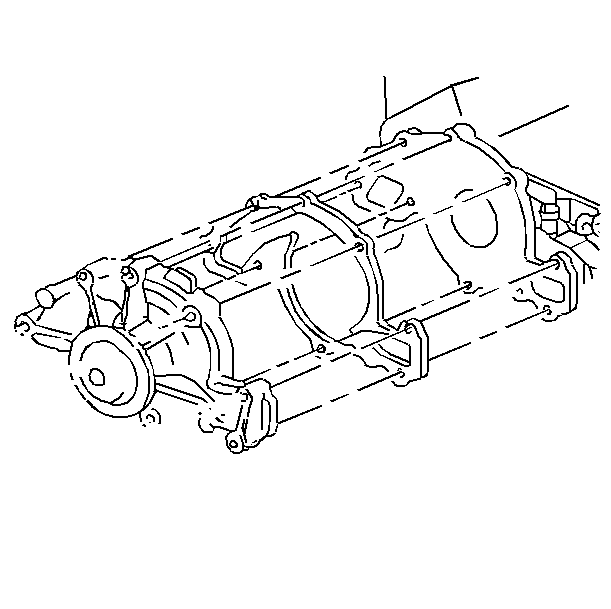
- Remove the water pump.
- Clean the gasket mating surfaces.
- Clean and inspect the water pump. Refer to Water Pump Cleaning and Inspection in Engine Mechanical - 3.8L.
Installation Procedure
- Using a new gasket, install the water pump on the engine.
- Install the water pump mounting bolts (1, 2).
- Install the water pump pulley and bolts.
- Install the drive belt. Refer to Drive Belt Replacement in Engine Mechanical - 3.8L.
- Fill the cooling system. Refer to Cooling System Draining and Filling .


Notice: Use the correct fastener in the correct location. Replacement fasteners must be the correct part number for that application. Fasteners requiring replacement or fasteners requiring the use of thread locking compound or sealant are identified in the service procedure. Do not use paints, lubricants, or corrosion inhibitors on fasteners or fastener joint surfaces unless specified. These coatings affect fastener torque and joint clamping force and may damage the fastener. Use the correct tightening sequence and specifications when installing fasteners in order to avoid damage to parts and systems.
Tighten
| • | Tighten the short bolts (1) to 15 N·m (11 lb ft). |
| • | Tighten the long bolts (2) to 30 N·m (22 lb ft). |

Tighten
Tighten the water pump pulley bolts to 13 N·m (115 lb in).
Water Pump Replacement LD8
Tools Required
| • | J 38816-A Water Pump Remover and Installer |
| • | J 38185 Hose Clamp Pliers |
Removal Procedure
- Drain the cooling system. Refer to Cooling System Draining and Filling .
- Remove the air cleaner assembly. Refer to Air Cleaner Assembly Replacement in Engine Controls - 4.6L.
- Remove the secondary air injection (AIR) shut-off valve. Refer to Secondary Air Injection Shut-Off Valve Outlet Pipe/Hose Replacement - Bank 1 in Engine Controls - 4.6L.
- Remove the oil level indicator tube nut.
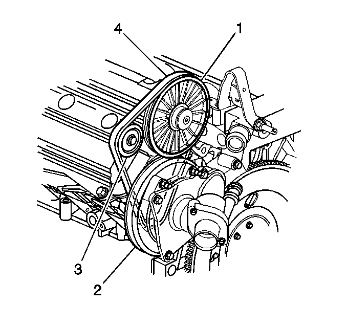
- Remove the water pump belt shield fasteners.
- Remove the water pump drive belt (4).
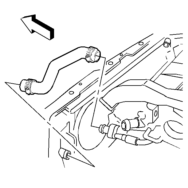
- Position the J 38185 to the clamp in order to remove the radiator outlet hose from the thermostat housing.
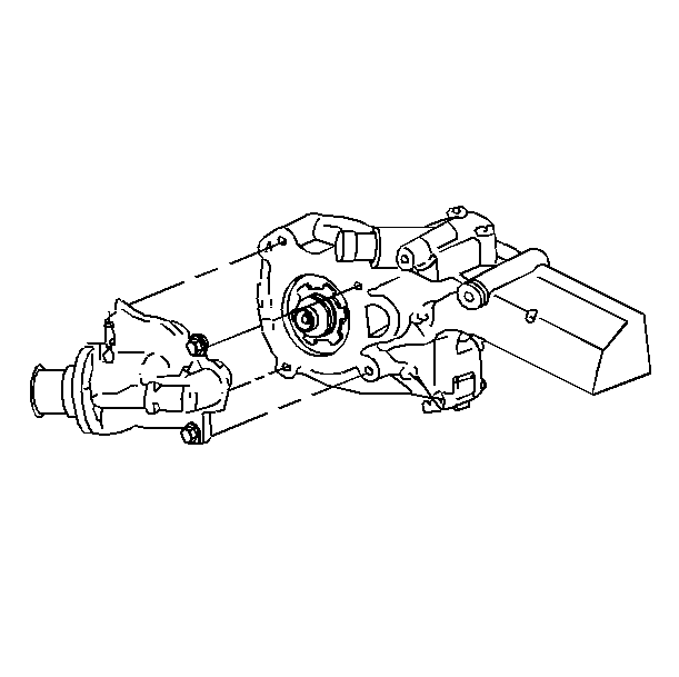
- Remove the water pump cover bolts.
- Remove the water pump cover.
- Disconnect the heater return hose.
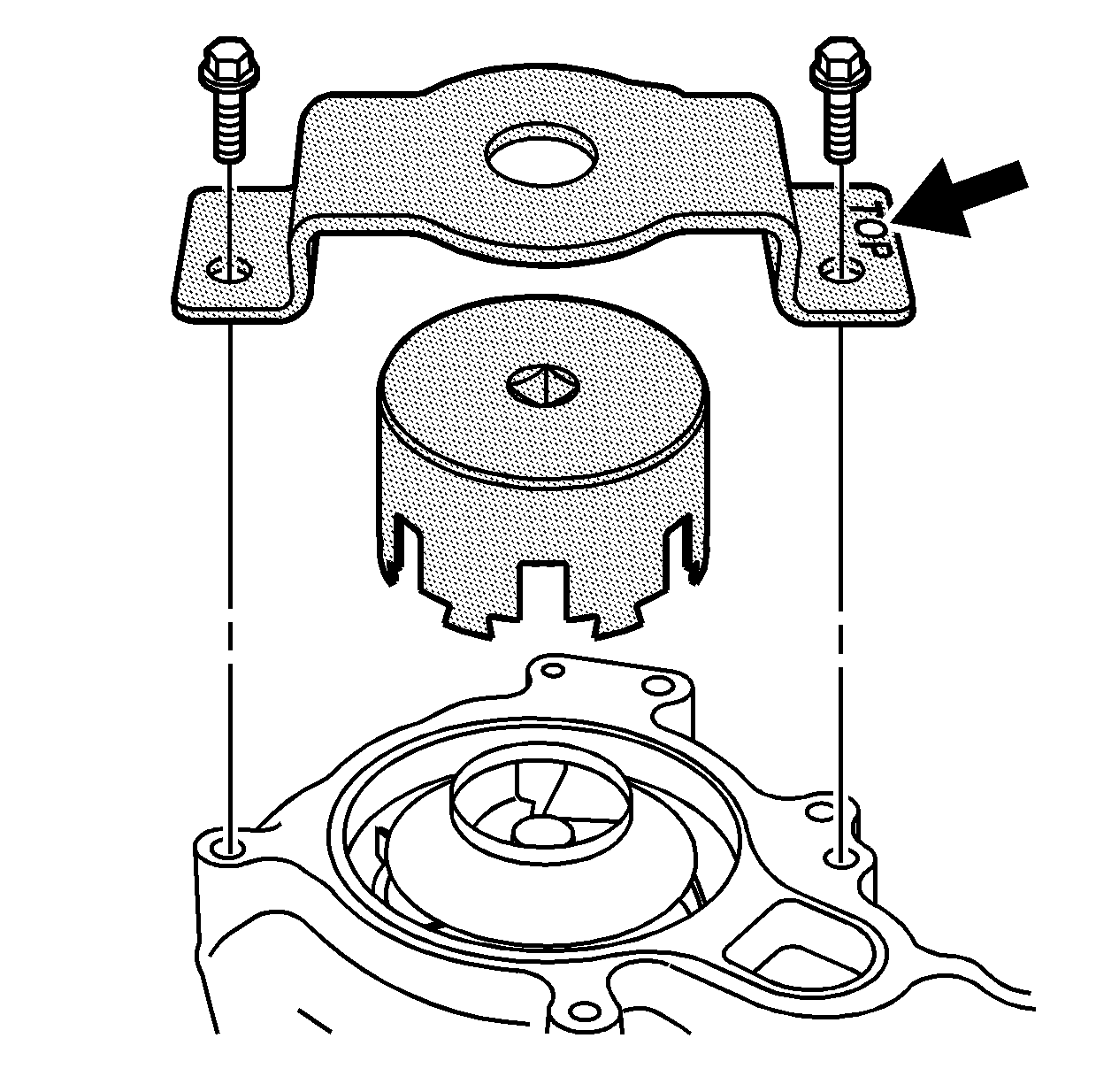
- Position the J 38816-A to the water pump locking ears.
- Fasten the support plate to the water housing crossover, to ensure proper engagement of the tool to the water pump locking ears.
- Using the J 38816-A , turn the pump clockwise in order to remove the pump from the housing.
- Remove the support plate from the water housing crossover.
- Remove the water pump from the vehicle.
- Remove the seal from the water crossover.
- Clean the sealing surfaces of the water housing crossover and the pump cover.
- Clean and inspect the water pump. Refer to Water Pump Cleaning and Inspection in Engine Mechanical - 4.6L.
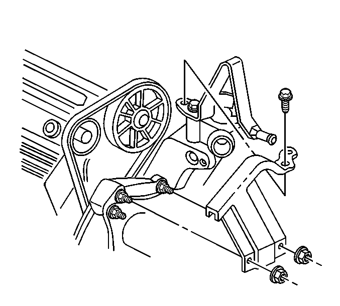
Remove the water pump belt shield.
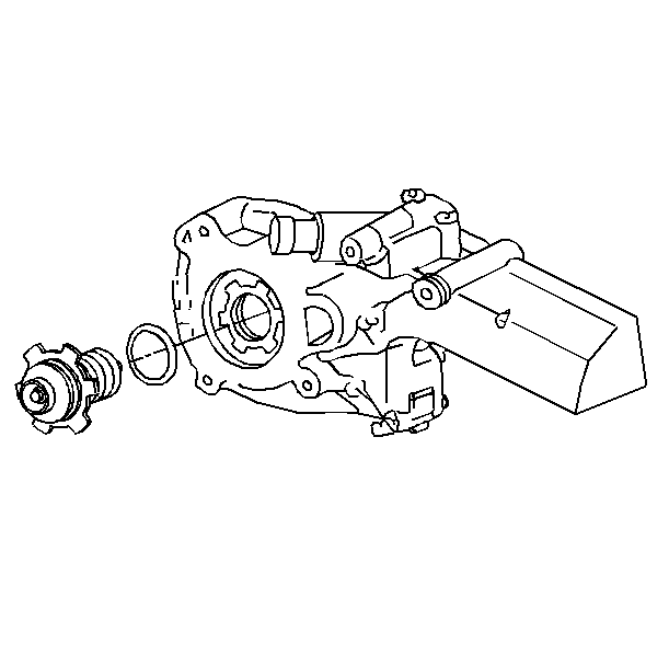
Installation Procedure
- Insert the seal into the recessed portion of the water crossover.
- Index the water pumps locking ears with the tangs in the water crossover.
- Position the J 38816-A to the water pump locking ears.
- Fasten the support plate to the water housing crossover, to ensure proper engagement of the tool to the water pump locking ears.
- Turn the J 38816-A counterclockwise.
- Remove the support plate from the water housing crossover.
- Connect the water pump cover to the heater return hose.
- Install the water pump cover to the water housing crossover.
- Install the water pump cover bolts.
- Position the J 38185 to the clamp in order to connect the radiator outlet hose to the thermostat housing.
- Install the water pump drive belt (4).
- Place the water pump belt shield in position.
- Install the water pump belt shield fasteners.
- Install the oil level indicator tube nut.
- Install the secondary AIR shut-off valve. Refer to Secondary Air Injection Shut-Off Valve Outlet Pipe/Hose Replacement - Bank 1 in Engine Controls - 4.6L.
- Install the air cleaner assembly. Refer to Air Cleaner Assembly Replacement in Engine Controls - 4.6L.
- Fill the cooling system. Refer to Cooling System Draining and Filling .

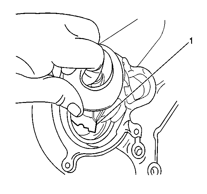
Important: The notched locking ear (1) must be in the 7 o'clock position.

Notice: Refer to Fastener Notice in the Preface section.
Tighten
Tighten the water pump to 100 N·m (74 lb ft).

Tighten
Tighten the water pump cover bolts to 10 N·m
(89 lb in).


Tighten
Tighten the water pump belt shield fasteners to
10 N·m (89 lb in).
Tighten
Tighten the oil level indicator tube nut to 10 N·m
(89 lb in).
