GM Service Manual Online
For 1990-2009 cars only
Makes
🢒
Pontiac
🢒
2005
🢒
Bonneville
🢒
Body
🢒
Wiring Systems
🢒 HVAC Schematics
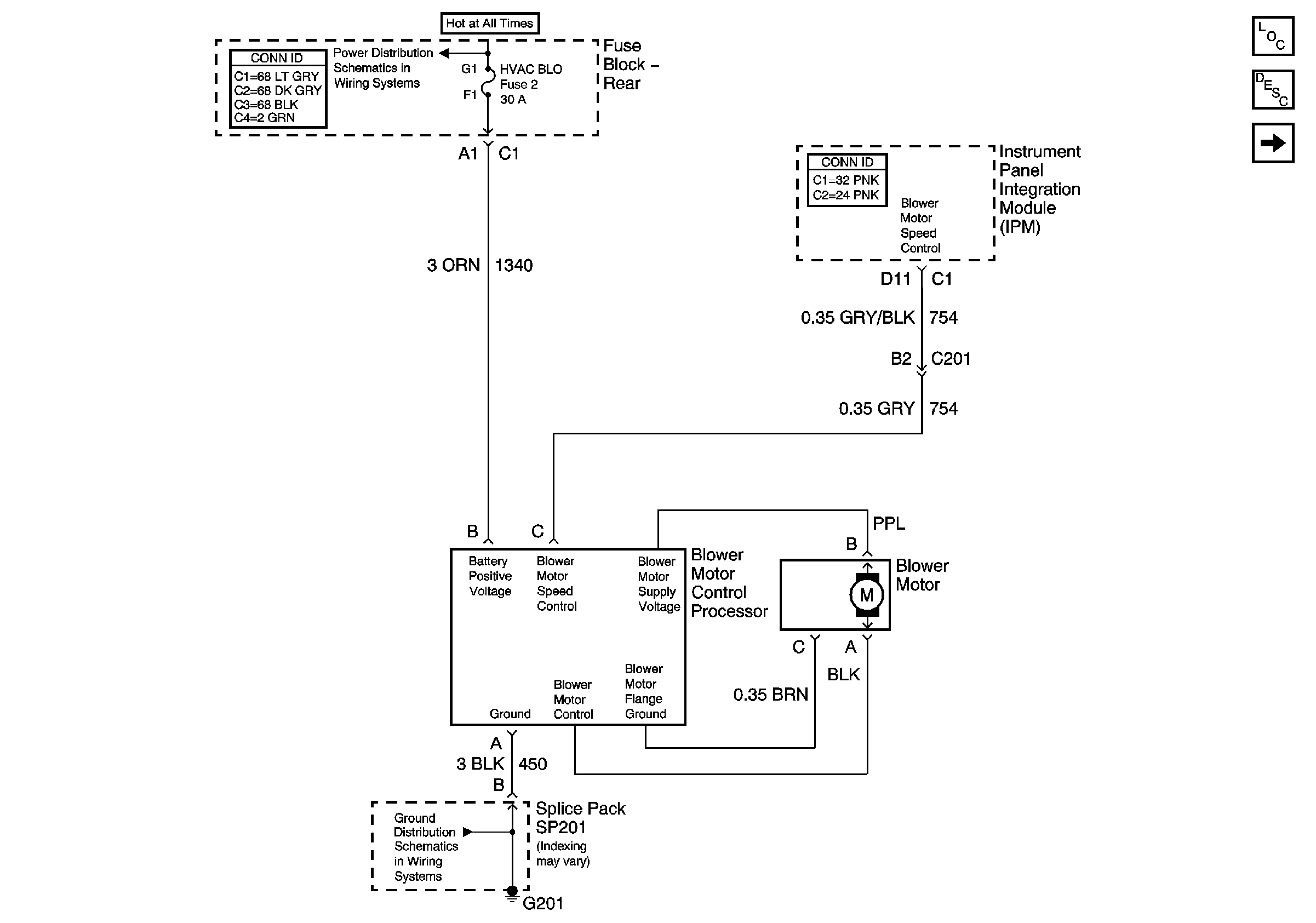
Figure
1:
Blower Control
Master Electrical Component List
Air Delivery Description and Operation
HVAC Control
HVAC BLO, AUDIO AMP, and SDAR Fuses
G201 - 1 of 2
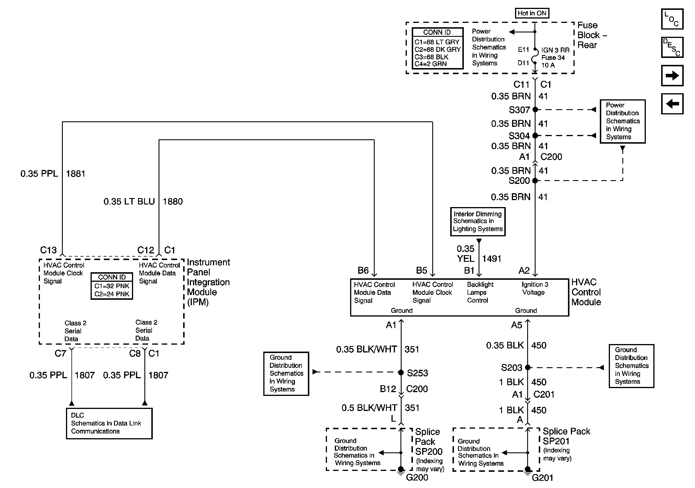
Figure
2:
HVAC Control
Master Electrical Component List
Air Delivery Description and Operation
Compressor Controls - 3.8L
Blower Control
Serial Data Class 2
G200
G200
IGN3 RR and ABS Fuses
I/P and Console Dimming
G201 - 1 of 2
IGN3 RR and ABS Fuses
G201 - 1 of 2
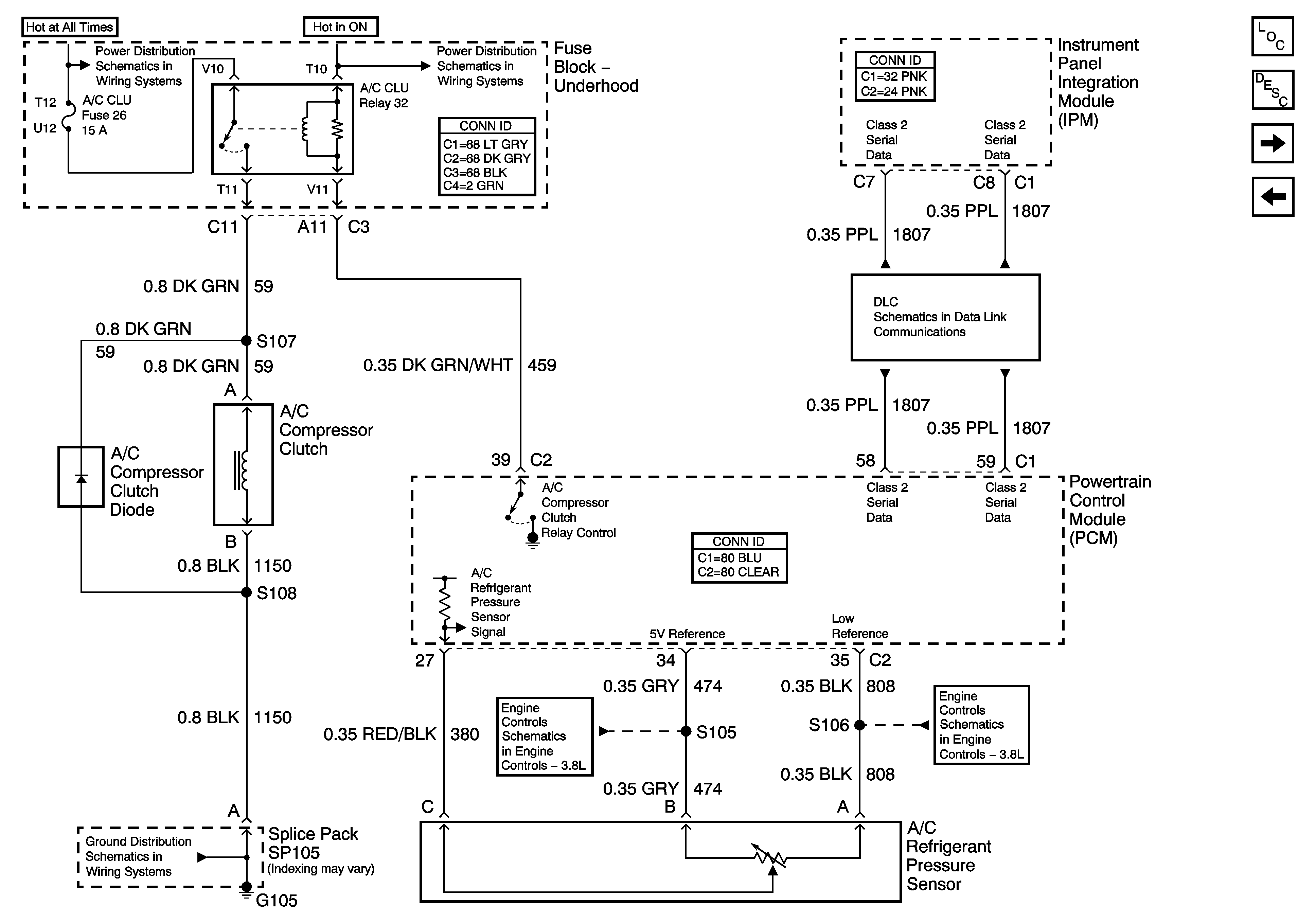
Figure
3:
Compressor Controls - 3.8L
Master Electrical Component List
Air Temperature Description and Operation
Compressor Controls - 4.6L
HVAC Control
START Circuit Breaker, HORN and A/C CLU Fuses - 3.8L
Serial Data Class 2
G104 and G105 - 3.8L
Fuel Sensor and EVAP Solenoid Controls
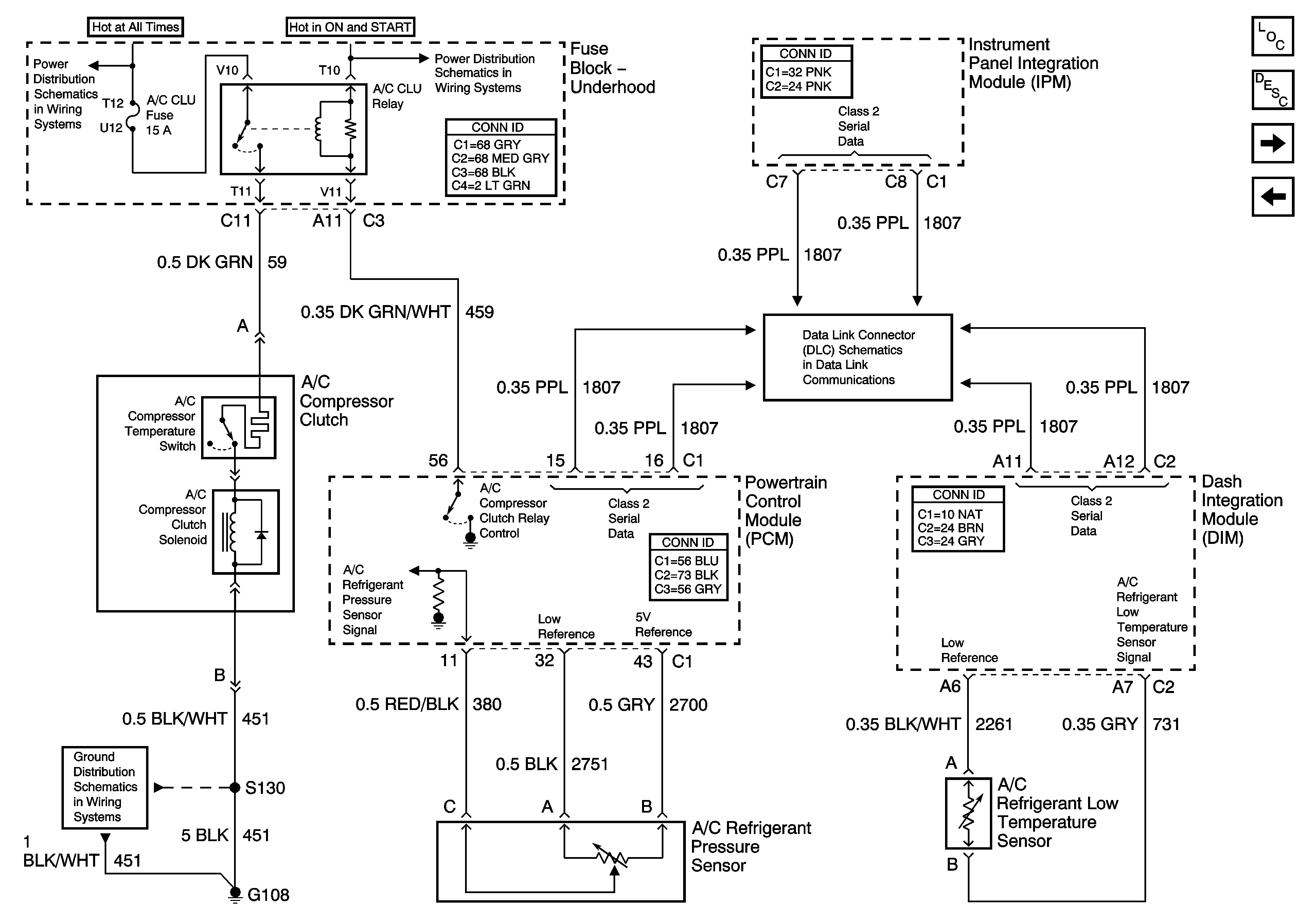
Figure
4:
Compressor Controls - 4.6L
Master Electrical Component List
Air Temperature Description and Operation
Air Delivery
Compressor Controls - 3.8L
START Circuit Breaker, HORN and A/C CLU Fuses - 3.8L
G108, G110, and G111 - 4.6L
Serial Data Class 2
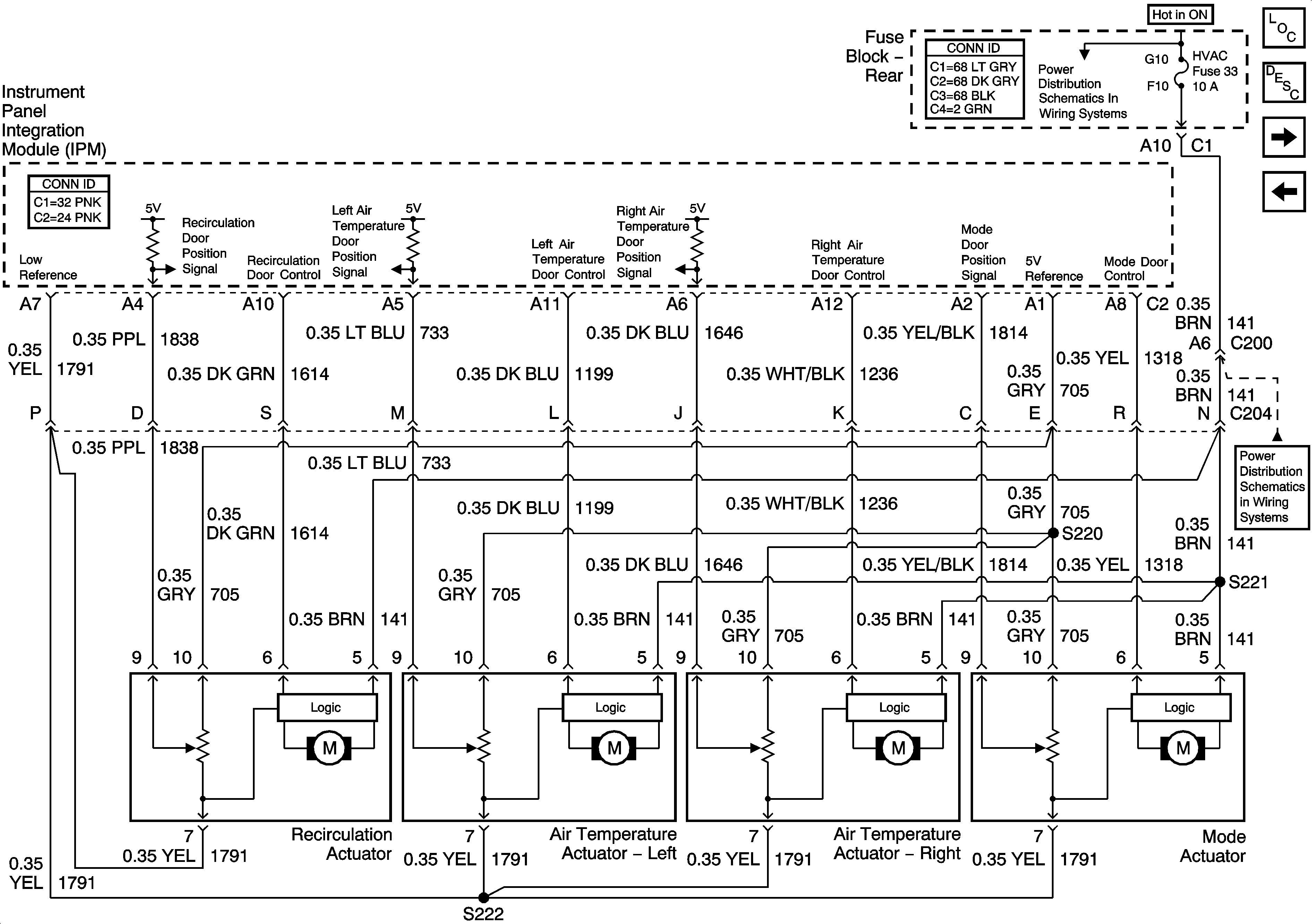
Figure
5:
Air Delivery
Master Electrical Component List
Air Temperature Description and Operation
Temperature Sensors
Compressor Controls - 4.6L
HVAC Fuse
HVAC Fuse
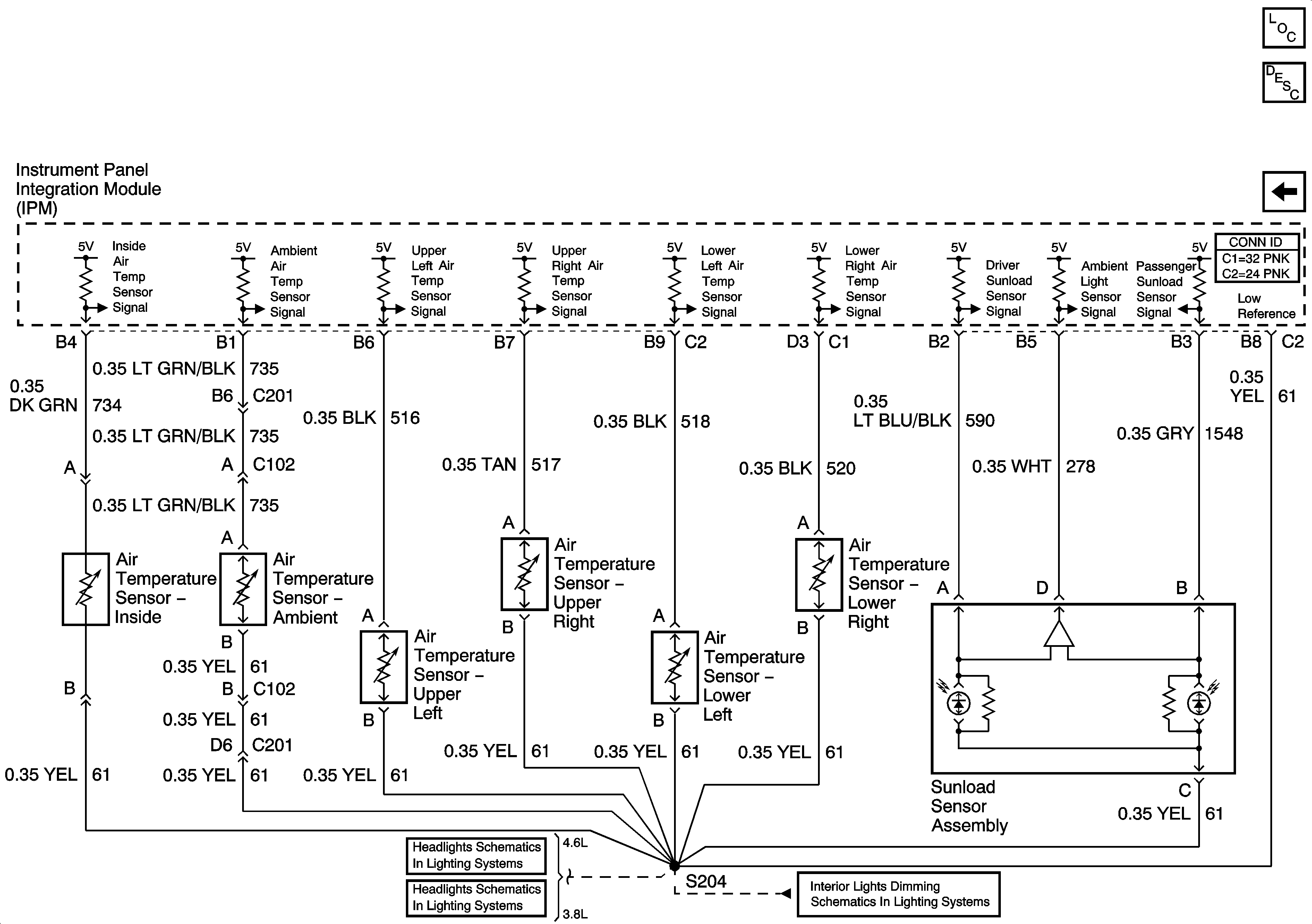
Figure
6:
Temperature Sensors
Master Electrical Component List
Air Temperature Description and Operation
Air Delivery
Headlamp Controls
Headlamp Controls
Dimming Control