SHIFT LEVER CABLE ROUTING REVISED REPLACEMENT PROCEDURE

TRANSMISSION APPLICATIONS: SUBJECT: ------------------------- ------- 1986-88 HM-282 MANUAL SHIFT SELECTOR CABLE ROUTING TRANSMISSION (RPO MG2)
TRANSMISSION MODELS: VEHICLE APPLICATIONS: ------------------- -------------------- ALL 1986-88 P CAR
SERVICE MANUAL UPDATE
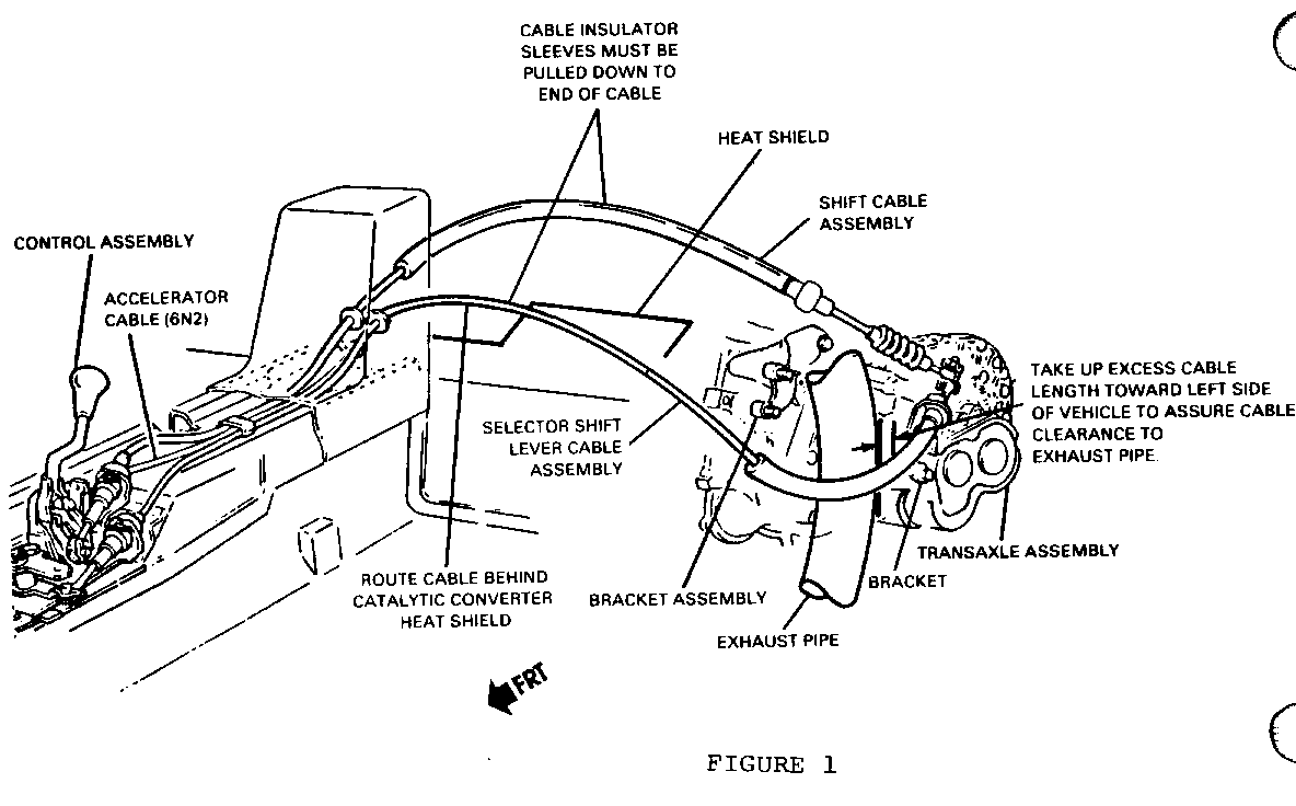
In the interest of customer satisfaction and due to a manufacturing requirement to address manual transmission selector shift lever cable routing, when replacing the cable, follow the revised removal and installation procedure as follows:
REMOVAL:
--------
1. Remove negative battery cable. 2. Remove shift knob. 3. Remove ash trays. 4. Remove console transmission shift plate. 5. Remove front floor console accessory switch mount plate. 6. Remove console trim pad. 7. Remove E. C. M. 8. Disconnect E. C. M. electrical connections. 9. Remove the two rear front floor console support retaining bolts. 10. Remove the carpet from the front floor console carpet retaining clips. 11. Remove front floor console support panel hole retainers. 12. Disconnect the ball stud and transmission selector shift cable retainer at transaxle. 13. Disconnect cable at shifter assembly. 14. Remove cable from vehicle.
INSTALLATION:
-------------
1. Install selector shift lever cable and route as shown in Figure 1.
NOTICE: - ROUTE SELECT CABLE DOWN BEHIND HEAT SHIELD. - DO NOT INSTALL CABLE THROUGH HINGE MOUNTED HOOK. - TAKE-UP EXCESS CABLE LENGTH TOWARD LEFT TO ASSURE CLEARANCE TO EXHAUST PIPE. - BE SURE TO PULL CABLE INSULATING SLEEVES DOWN TO THE END OF CABLE.
2. Install cable at shifter assembly. 3. Connect the ball stud and transmission selector shift. 4. Install front floor console support panel hole retainers. 5. Position the carpet into the front floor console carpet retaining clips. 6. Install the two rear front floor console support retaining bolts. Tighten bolts to 1.6 Nm. (14 lbs. in.). 7. Connect the E.C.M. electrical connectors. 8. Install E.C.M. 9. Install console trim pad. Tighten bolts to 1.6 Nm. (14 lbs. in.). 10. Install front floor console accessory switch mount plate. 11. Install console transmission shift plate. Tighten bolts to 1.6 Nm. (14 lbs. in.). 12. Install ash trays. 13. Install shift knob. 14. Install negative battery cable.

General Motors bulletins are intended for use by professional technicians, not a "do-it-yourselfer". They are written to inform those technicians of conditions that may occur on some vehicles, or to provide information that could assist in the proper service of a vehicle. Properly trained technicians have the equipment, tools, safety instructions and know-how to do a job properly and safely. If a condition is described, do not assume that the bulletin applies to your vehicle, or that your vehicle will have that condition. See a General Motors dealer servicing your brand of General Motors vehicle for information on whether your vehicle may benefit from the information.
