CAMPAIGN: LACK OF ADEQUATE SERVICE OR MAINTENANCE

Subject: Lack of Adequate Service or Maintenance
Models: 1985-88 Pontiac Fiero Models with 2.8L V6 Engines (RPO L44)
TO: ALL GENERAL MOTORS DEALERS
General Motors of Canada has determined that a defect which relates to motor vehicle safety exists in 1985-88 Pontiac Fiero model vehicles with 2.BL V6 engines (RPO L44).
An interaction of the engine compartment environment in 1985-88 Pontiac Fieros and maintenance or service related factors results in the potential for engine compartment fires.
If combustible materials come in contact with the exhaust manifold, an engine compartment fire can result. Engine compartment fires can spread to the passenger compartment and cause injury to occupants.
To greatly reduce the possibility of this condition occurring, all vehicles will have changes made in their underhood environment. Specifically, all vehicles will have a manifold deflector installed, a minor change to decklid sealing, a PCV system modification and a general inspection (and repair as necessary) of underhood fluid and wiring systems. Additionally 1985-86 model year vehicles will have a new exhaust manifold installed to bring them up to 1987-88 specifications.
VEHICLES INVOLVED:
Involved are 1985-88 Pontiac Fiero model vehicles with 2.8L V6 engine (RPO L44) produced within the following VIN breakpoints:
Model Year Plant Beginning Up To And Including ----- ---- ------- --------- ----------------------- P 1985 Pontiac FP200001 FP276370 P 1986 Pontiac GP200006 GP283973 P 1987 Pontiac HP200006 HP246579 P 1988 Pontiac JP200003 JP226402
All affected vehicles have been identified by the VIN listing provided to involved dealers with this bulletin. Any dealer not receiving a listing was not shipped any of the affected vehicles.
DEALER CAMPAIGN RESPONSIBILITY:
Dealers are to perform this campaign on all involved vehicles at no charge to owners, regardless of kilometres traveled, age of vehicle, or ownership, from this time forward.
Whenever a vehicle subject to this campaign is taken into your new or used vehicle inventory, or it is in your dealership for service, you are to ensure the campaign correction has been made before selling or releasing the vehicle.
Owners of vehicles recently sold from your new vehicle inventory are to be contacted by the dealer, and arrangements made to make the required modification according to instructions contained in this bulletin.
CAMPAIGN PROCEDURE:
Refer to Section 4 of the Service Policies and Procedures Manual for the detailed procedure on handling Product Campaigns. Dealers are requested to complete the campaign on all transfers as soon as possible.
OWNER NOTIFICATION:
All owners of record at the time of campaign release are shown on the attached computer listing and have been notified by first class mail from General Motors. The listings provided are for campaign activity only and should not be used for any other purpose.
PARTS INFORMATION:
Parts required to complete this campaign should be ordered through regular channels, as follows:
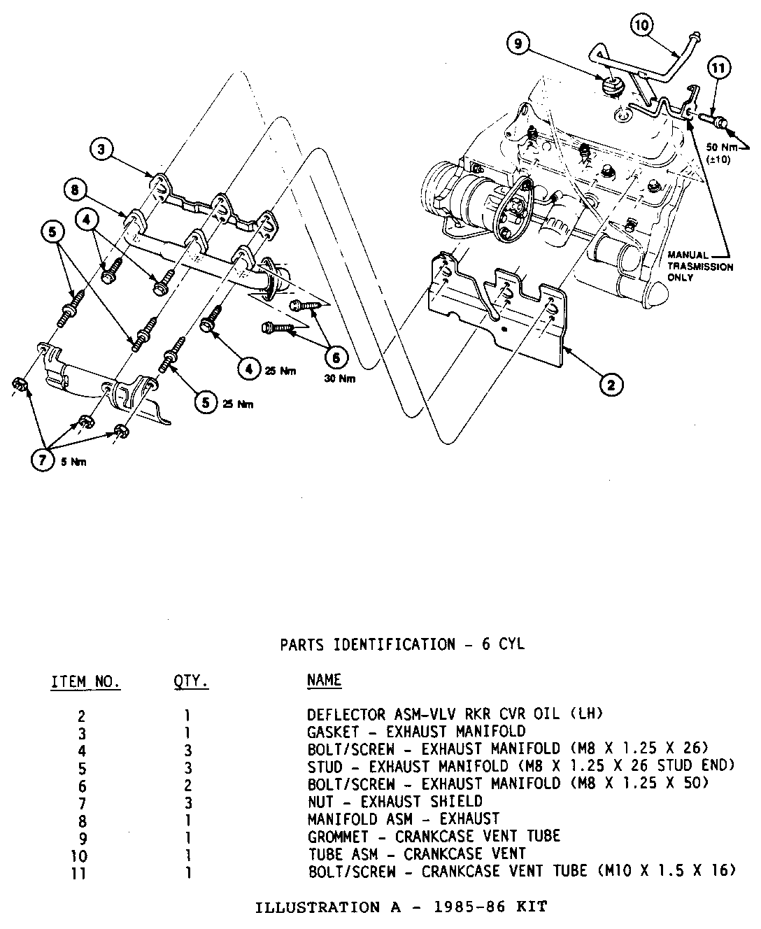
Part Quantity/ Description Number Vehicle ------------------ -------- --------- Service Kit (1985-86) (ILLUSTRATION A) 10154785 1
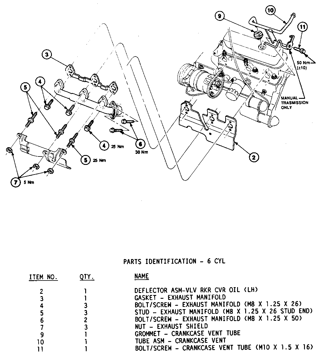
Service Kit (1987-88) (ILLUSTRATION B) 10154787 1
Breakdown of the specific parts included in these kits are shown on the applicable illustrations.
Additional parts necessary to correct engine compartment fluid leaks, or cooling system discrepancies, etc. , are to be ordered from GMSPO as required from the appropriate service parts catalogue. Please note also that campaign 8R12 "ENGINE SPLASH SHIELDS POTENTIAL INTERFERENCE WITH COOLANT HOSES" should also be done if it is still outstanding.
PARTS AND LABOUR CLAIM INFORMATION:
Credit for the campaign work performed will be paid upon receipt of a properly completed campaign claim card, RAPID terminal or DCS transmission in accordance with the following:
Repair Code Description Time Allowance ----------- ----------------------- ---------------- 2A Install Deflector Package 3.2 Vehicle Without A/C (1985-88)
3A Install Deflector Package 5.1 Vehicle With A/C (1985-88)
T8036 Owner Reimbursement On Previous Repairs
The labour hours above include time for pressurizing and inspecting the cooling and fuel system.
Time allowance includes 0.1 hour for dealer administrative detail associated with this campaign. Parts credit will be based on dealer net plus 30% to cover parts handling.
IF THE INSPECTION PROCEDURE REVEALS ADDITIONAL OPERATIONS ARE NECESSARY, THE APPROPRIATE "T" LABOUR OPERATIONS SHOULD BE SELECTED FROM FOLLOWING CHARTS. THESE SHOULD ONLY BE USED IN CONJUNCTION WITH 2A AND 3A.
EXHAUST SYSTEM Labour Labour Description Hours Operation -------------- ------- ---------- Shield Exhaust/Replace .3 T3244 Each Additional .2
Crossover Pipe .5 T1629
COOLING SYSTEM Labour Labour Description Hours Operation --------------------------- ------ ----------
Clamp Radiator Hose/Replace .2 T3203 Add: To Replace Each Additional .1
Coolant Hoses/Replace Upper .6 T3204
Coolant Hoses/Replace Lower .6 T3205
Replace Both Upper & Lower 1.0 T3206
Pump/Gasket, Coolant/Replace 2.1 T1630
Sensor Coolant Temperature .4 T3213
Coolant Fan Switch/Replace .3 T3215
Engine Coolant Temp. Switch/Replace .3 T3216
Thermostat Housing and/or Gasket/Replace .4 T3242
Heater Pipe Clamp/Replace .3 T3229
Hose, Htr. Pipe to Eng. Comp. Inlet/Replace .4 T3232
Hose, Eng. Comp. Inlet to Engine/Replace .4 T3233
Hose, Htr. Pipe to Engine Outlet/Replace .4 T3234
Blade/Motor Cooling Fan/Replace .6 T3235
Relay, Cooling Fan/Replace .3 T3236
Wiring and/or Connector/Repair .5 T3237
Hose, TBI Coolant/Replace .3 T1631
Relay, Engine Blower .2 T1632
Motor and/or Fan, Engine Blower .4 T1633
LUBRICATION SYSTEM
Rocker Gasket - Right/Rear 2.0 T1634 Left/Forward 2.3 T1635 Both 2.6 T1636
FUEL SYSTEM Labour Labour Description Hours Operation ---------------------- ------ ----------
Seals, Fuel Feed & Return Pipes .3 T1637 Pipe, Fuel Pump to Throttle Body Unit/Replace .3 T3312 Pipe, Fuel/Repair .6 T1626 O-Ring, Cold Start Valve/Replace 1.0 T1638
TRANSMISSION OIL COOLER
Upper Trans. Oil Cooler Hose/Replace .2 T3180 Lower Trans. Oil Cooler Hose/Replace .2 T3181 Both Trans. Oil Cooler Hose/Replace .3 T3182
IGNITION SYSTEM/ENGINE COMPARTMENT WIRING
Wiring - Routing/Clips .2 T1627
BOLT BREAKAGE
Exhaust Manifold (Each Bolt/Stud) .6 T1639
CAR RENTAL
Car Rental - Parts Delay --- T3256
NOTE: CAR RENTAL (up to $40.00 per day for a maximum of 2 days) IS TO COVER PARTS DELAYS. CLAIMS IN EXCESS OF 2 DAYS WILL REQUIRE BDC REVIEW AND AUTHORIZATION.
REIMBURSEMENTS
Claims for customer reimbursements on previously paid repairs related to ONLY Exhaust Manifold and Exhaust Manifold Fastener Repairs will be considered.
Owners should present documentation which reasonably confirms the amount of unreimbursed repair expense, a description of the repair, the date of the repair, and the person or entity performing the repair.
Review the owner's documentation, and process under Repair Code 6A (authorization is required).
SERVICE PROCEDURE:
To reduce the effects of fluid leaks which may lead to engine compartment fires, GM dealers will do the following at no charge:
1. INSTALL EXHAUST MANIFOLD DEFLECTOR
a. Remove outboard grille panels, and disconnect BOTH positive and negative battery cables (remove the battery on vehicles equipped with air conditioning).
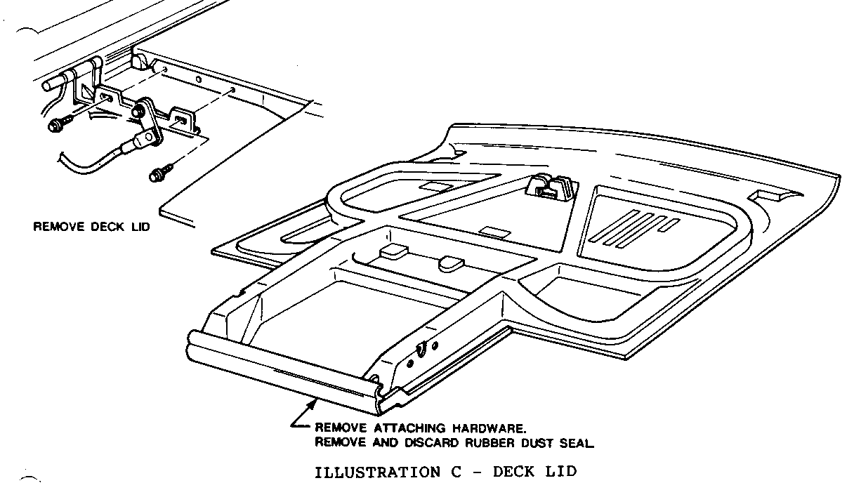
b. Remove rear engine compartment lid. Remove rubber dust seal and retaining clips from leading edge (front) of decklid assembly (and leave off) (ILLUSTRATION C).
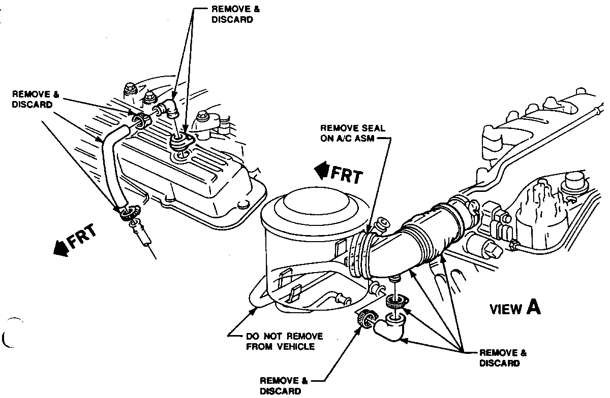
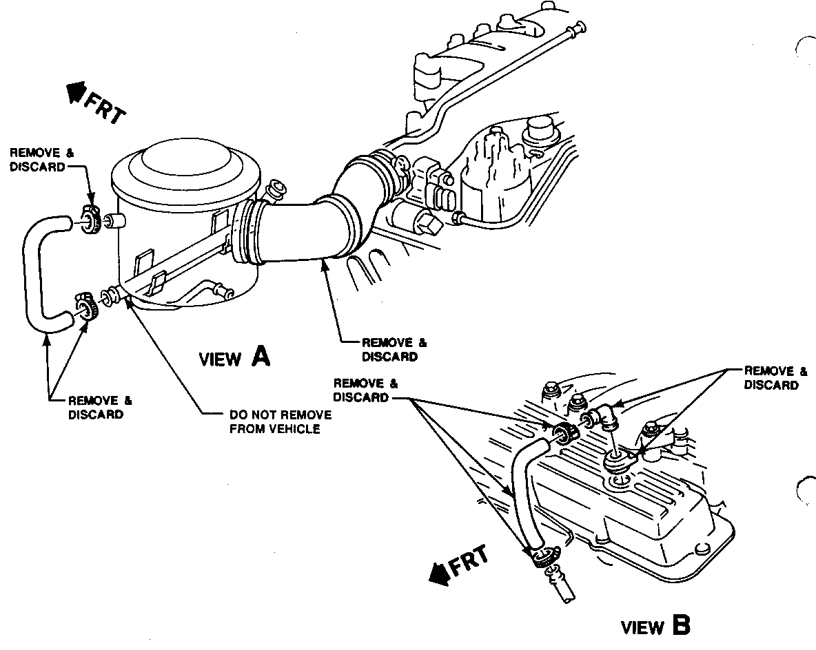
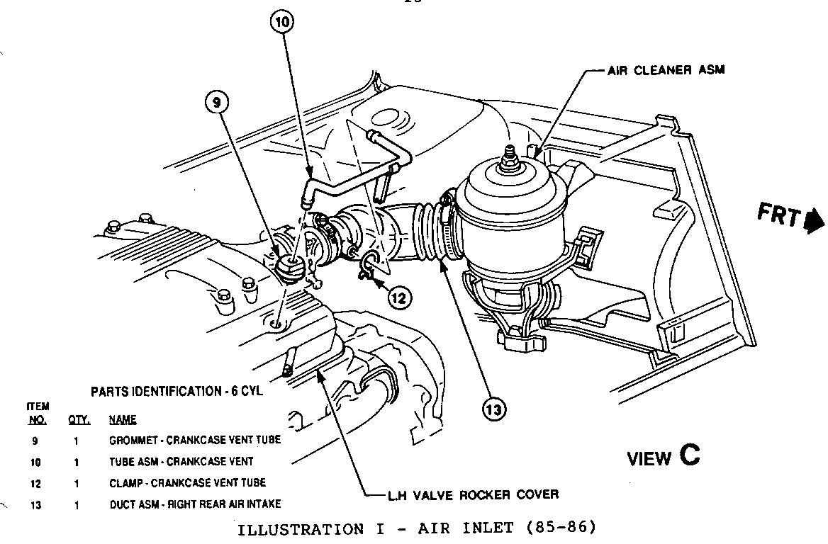
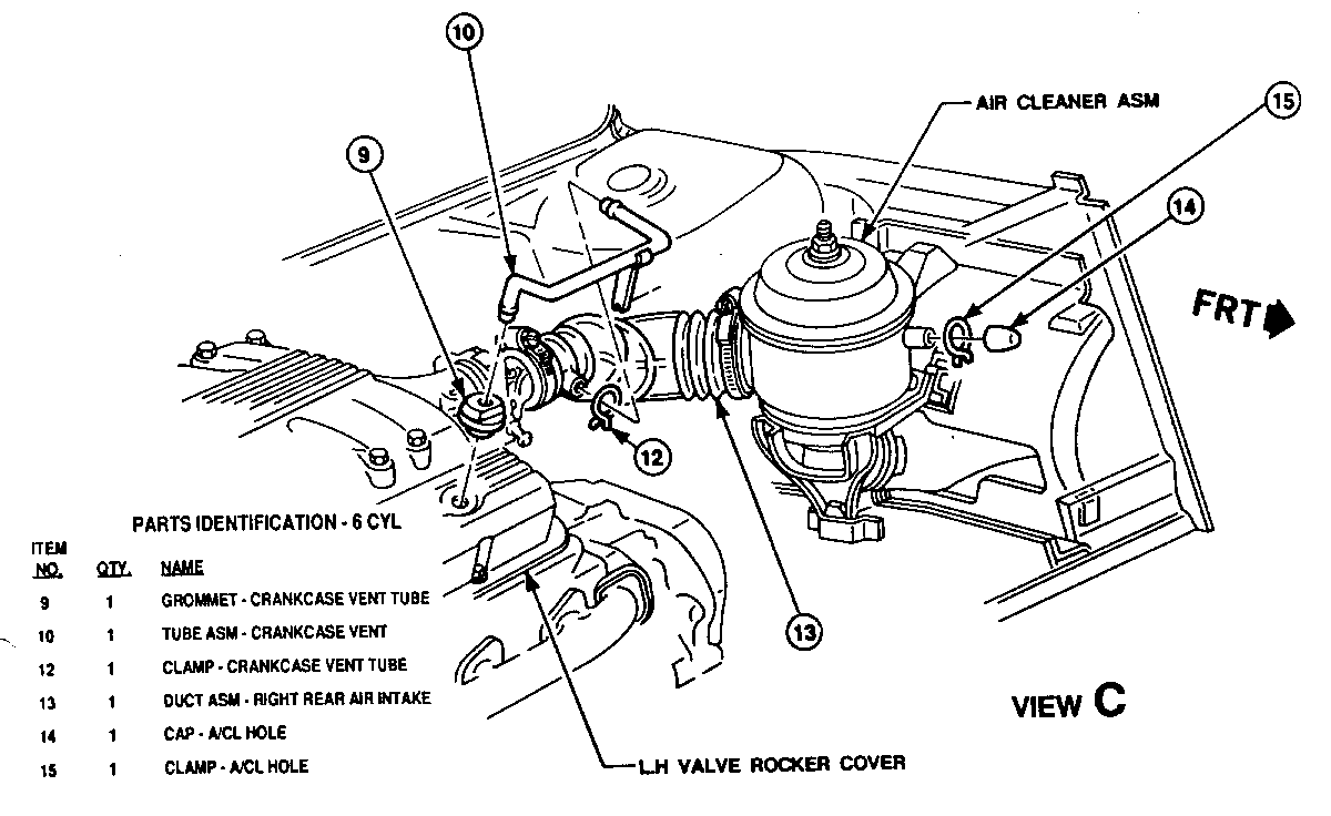
c. Remove air intake duct assembly (ILLUSTRATION D & E). Remove foam rubber seal on air cleaner housing neck (85-86 only). Remove PCV vent tube elbow(s), clamps and hoses at engine and air cleaner. DO NOT remove PCV vent tube mounted on forward engine compartment wall.
d. Apply penetrating oil to all bolts and studs of the forward exhaust manifold. THIS STEP IS VERY IMPORTANT TO AVOID STUD BREAKAGE-LATER ON.
e. Remove exhaust manifold to crossover bolts.
f. Disconnect upper engine strut.
9. Raise vehicle.
h. Remove converter down pipe to crossover bolts.
i. Remove converter heat shield.
j. Perform the following steps on air conditioned vehicles:
1. Remove air conditioning compressor shield. 2. Disconnect A/C belt and wires from compressor. 3. Remove A/C compressor mount bolts and lower A/C adjusting bracket. 4. Lower vehicle. 5. Remove upper A/C compressor mount bracket. 6. Raise vehicle.
k. Install jack stands under rear of vehicle to allow cradle to be lowered slightly.
l. Install jack stand under cradle and remove forward cradle bolts and nuts; lower cradle slowly approximately SIX (6) inches below mountings (for better access to front exhaust manifold). Do not lower more than SIX (6) inches.
m. Remove outer exhaust manifold heat shield.
n. Remove forward manifold bolts and studs. Best results will be obtain- ed by:
- Applying penetrating oil early (Step C) and reapply now.
-In the event of bolt breakage, a service tool for piloting easy-outs (WITHOUT removing the cylinder head) has been provided. Kent-Moore Tool J-38782 has been provided to all involved dealers.
o. Clean exhaust manifold gasket surfaces. Inspect 1987-88 exhaust manifold for any evidence of cracking or significant warpage. The 1985-86 vehicles will have a new (slotted flange) manifold installed if not already equipped.
p. Cut wire harness bracket off engine coolant pipe to avoid interference with new shield.
q. Stack manifold deflector, gasket and manifold over new bolts and install (position on head using top bolts) using torque values described in ILLUSTRATION A & B.
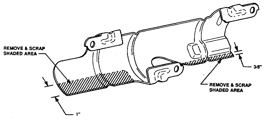
r. Modify (ILLUSTRATION F) and install outer manifold heat shield (dimensions for modification on illustration).
s. Reattach cradle and torque cradle bolts according to the applicable Fiero Service Manual procedure. Remove jack stands. Lower vehicle.
t. Install crossover to manifold bolts using torque values described in ILLUSTRATION A & B.
u. Install upper A/C compressor mount bracket.
v. Install side heat shield (A/C equipped vehicles), and install battery (to be connected later).
w. Raise vehicle.
x. Install A/C compressor, attach wires, lower adjusting bracket and belt (do adjustment at this time).
y. Install converter down pipe to crossover bolts (installing new seal provided in the kit).
z. Install A/C compressor heat shield (A/C equipped vehicles), converter heat shield.
NOTE: THE STEPS BELOW ARE INSPECTION ITEMS. IT IS IMPERATIVE THAT CARE BE EXERCISED IN INSPECTION. THE PARTICULAR ITEMS HAVE BEEN CHOSEN DUE TO THEIR POTENTIAL ASSOCIATION WITH UNDERHOOD FIRE. SEE THE NOTES ON EACH STEP FOR THE TYPES OF REPAIRS AUTHORIZED.
PLEASE NOTIFY YOUR CUSTOMER OF ANY ISSUES NOT FIXED IN YOUR INSPECTION WHICH WILL BE HIS/HER RESPONSIBILITY.
ANY ISSUES NOT SPECIFICALLY AUTHORIZED IN THIS BULLETIN MAY BE DISCUSSED WITH YOUR APPROPRIATE BDC CONTACT PERSON WITH SERVICE RESPONSIBILITY.
aa. Conduct inspection underneath the vehicle for:
0 Any indication of transmission oil cooler hose leakage.
0 Interference between right-hand wheelhouse splash shield and coolant hose. IF CAMPAIGN 8Rl2 HAS NOT BEEN PERFORMED, DO IT NOW.
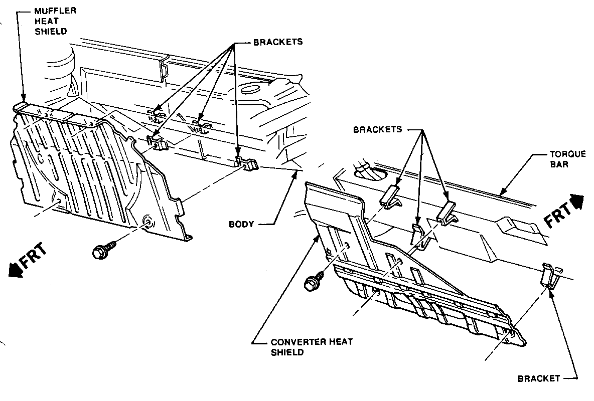
0 Any missing heat shield for this application (ILLUSTRATION G).
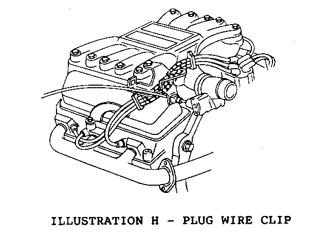
bb. Lower vehicle. Remove plug wire clip, slide conduit up, and reinstall clip, connect wires to spark plugs (ILLUSTRATION H). The clip is no longer seated on the bracket and should be repositioned above the edge of the rocker cover. Bracket should be removed.
cc. Loosen shift cable bracket bolt (already installed on manual transmission equipped vehicles; bolt supplied in kit for automatic transmission equipped vehicles).
dd. Install new PCV grommet in the forward rocker cover, new air intake duct (w/clamps) and vent tube/bracket assembly. Orient grommet with flat side facing forward (ILLUSTRATION I & J). Position tube/bracket assembly under shift cable bracket bolt (manual transmissions) or install bolt supplied kit (automatic transmissions). For 1987-88 vehicles, install rubber cap with clamp on air cleaner housing.
ee. Connect engine strut and torque according to the applicable Fiero Service Manual procedure.
ff. Install new oil filler cap on rear rocker cover.
gg. Inspect battery cable and routing for any signs of chafing or wear. Replace or reroute as necessary.
hh. Connect battery and install engine compartment side outer grill.
ii. Install J34730-1 (Fuel Pressure Gauge).
jj. Pressurize fuel system to approximately 40 psi by running fuel pump with key on. Using pressure gauge on schrader valve, monitor to check if system holds pressure. Observe coldstart and port injector connections at fuel rail as well as coupled fuel hose fittings for any sign of leakage. Repair as necessary.
kk. Pressurize HOT coolant system to 15 psi using a hand pump. Observe throttle body heater pipes at connection to throttle body for any signs of leakage. Repair any coolant leakage observed here or elsewhere within the engine compartment.
NOTE: STEP 2 IS AN INSPECTION ITEM. IT IS IMPERATIVE THAT CARE BE EXERCISED IN INSPECTION. THE PARTICULAR ITEMS HAVE BEEN CHOSEN DUE TO THEIR POTENTIAL ASSOCIATION WITH UNDERHOOD FIRE. SEE THE NOTES ON EACH STEP FOR THE TYPES OF REPAIRS AUTHORIZED.
PLEASE NOTIFY YOUR CUSTOMER OF ANY ISSUES NOT FIXED IN YOUR INSPECTION WHICH WILL BE HIS/HER RESPONSIBILITY.
ANY ISSUES NOT SPECIFICALLY AUTHORIZED IN THIS BULLETIN MAY BE DISCUSSED WITH YOUR APPROPRIATE BDC CONTACT PERSON WITH SERVICE RESPONSIBILITY.
2. INSPECTION
Conduct general inspection of vehicle for any other potential fire related issues, specifically:
- Rocker cover leakage from either gasket surface or PCV valve grommet leakage should be repaired if significant. SEEPAGE IS NOT SIGNIFICANT.
- Improper wiring harness, coolant hose, or fuel line routings which are resulting in chafing of a serious nature should be rerouted (and repaired if necessary).
- Inspect cooling fan operation (on 1985-87 the engine compartment blower fan also should be inspected). Replacement of relay, coolant switch, wiring or fan is authorized to make functional.
3. Install engine compartment lid.
4. Install Campaign Identification Label.
INSTALLATION OF CAMPAIGN IDENTIFICATION LABEL
Clean surface of radiator upper mounting panel and apply a Campaign Identification Label. Make sure the correct campaign number is inserted on the label. This will indicate that the campaign has been completed.
Dear General Motors Customer:
General Motors of Canada has determined that a defect which relates to motor vehicle safety exists in 1985-88 Pontiac Fiero model vehicles with 2.8L V6 engines.
An interaction of the engine compartment environment in 1985-88 Pontiac Fieros and maintenance or service related factors results in the potential for engine compartment fires.
If combustible materials come in contact with the exhaust manifold, an engine compartment fire can result. Engine compartment fires can spread to the passenger compartment and cause injury to occupants.
To reduce the possibility of this condition occurring, all vehicles will have changes made in their underhood environment. Specifically, all vehicles will have a manifold deflector installed, a minor change to decklid sealing, and a general inspection (and repair as necessary) of underhood fluid and wiring systems. Additionally 1985-86 model year vehicles will have a new exhaust manifold installed to bring them up to 1987-88 specifications.
Please contact your GM dealer as soon as possible to arrange a service date.
This letter identifies your vehicle. Presentation of this letter to your dealer will assist their Service personnel in completing the necessary correction to your vehicle in the shortest possible time.
Further assistance, if required, may be obtained from our Customer Assistance Centre, toll free, by calling 1-800-263-3777, or if you live in Quebec, 1-800-263-7854.
We are sorry to cause you this inconvenience; however, we have taken this action in the interest of your continued satisfaction with our products.
Customer Support Department General Motors of Canada Limited
General Motors bulletins are intended for use by professional technicians, not a "do-it-yourselfer". They are written to inform those technicians of conditions that may occur on some vehicles, or to provide information that could assist in the proper service of a vehicle. Properly trained technicians have the equipment, tools, safety instructions and know-how to do a job properly and safely. If a condition is described, do not assume that the bulletin applies to your vehicle, or that your vehicle will have that condition. See a General Motors dealer servicing your brand of General Motors vehicle for information on whether your vehicle may benefit from the information.
