BURNED 3-4 CLUTCH/HI 2-3 SHIFT 700 R4 A/T

"Please discard previous bulletin 84-7-18 due to text change."
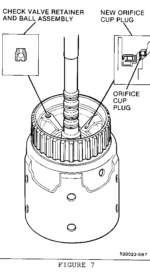
Starting production of all 1985 THM 700-R4 transmissions an air bleed orifice cup plug was added to the input clutch housing (Figure 7). Due to this change the procedure listed below for air checking the 3-4 clutch piston and the check ball has been revised.
Some 1982 thru 1984 THM 700-R4 transmissions may exhibit a burned 3-4 clutch, and/or high 2-3 shifts. (The high 2-3 shifts are experienced on C, K, and G truck gas/diesel applications only).
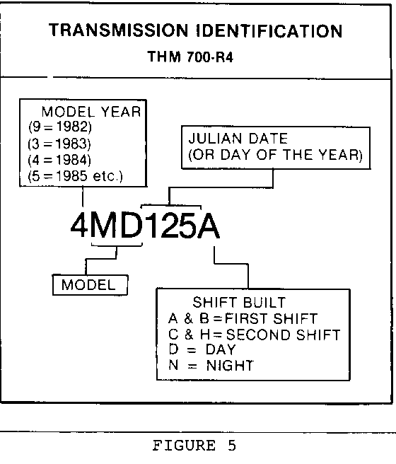
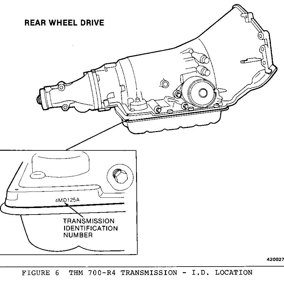
Starting January 15, (Julian date 015) 1984, all THM 700-R4 transmissions were built with a new input housing and shaft assembly and control valve body assembly. Refer to Figures 5 and 6 for Julian date location.
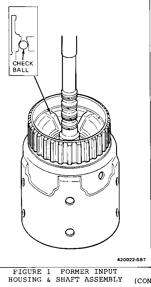
The former input housing and shaft assembly had a check ball seat drilled into the housing. A check ball was installed into this hold and the opening was then staked to retain the ball (see Figure 1).
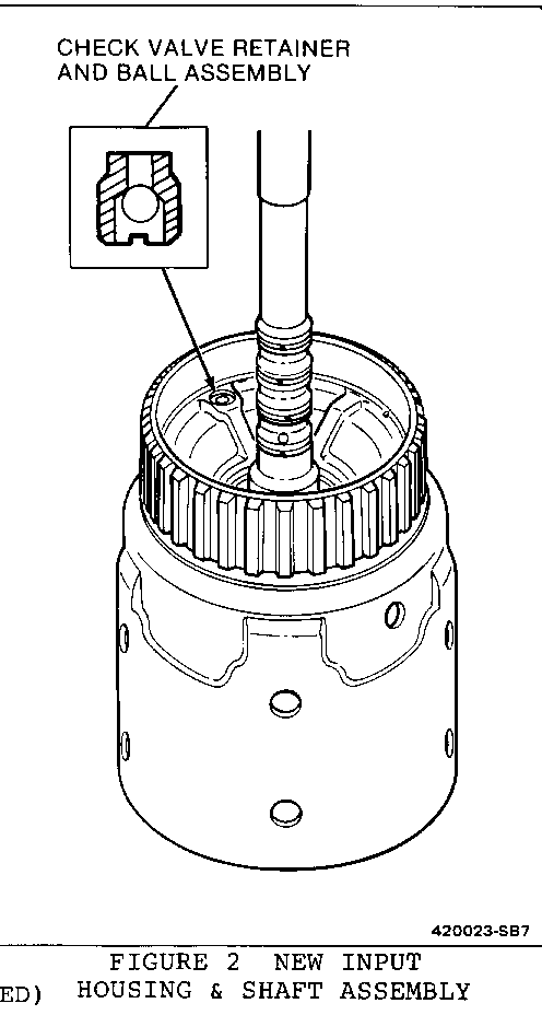
The new input housing and shaft assembly has a check valve retainer and ball assembly which is pressed into the housing (see Figure 2).
Only the new input housing and shaft assembly is available for service. Refer to the parts manual for correct part numbers and model application.
Also, for the burned 3-4 clutch, air check the 3rd and 4th clutch piston and the check ball in the input clutch housing for leaks by following the procedure as listed below:
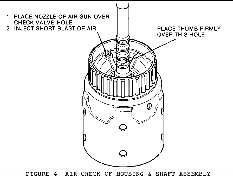
1. If you have an input clutch housing which does not have the new air bleed orifice cup plug (Figure 2) then, place your thumb firmly over the oil hole on the turbine shaft shown in Figure 4.
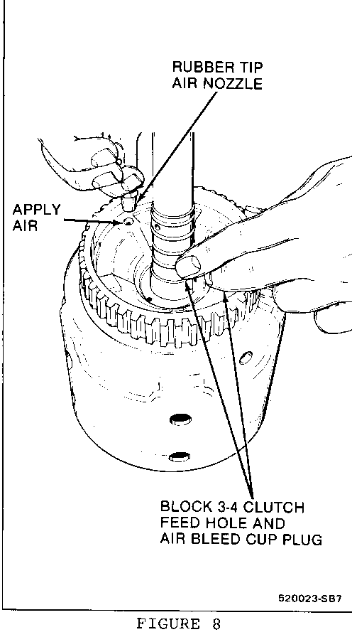
2. If you have an input clutch housing which has the new air bleed orifice cup plug (Figure 7) then, place your middle finger over the air bleed orifice cup plug and your index finger over the oil hole on the turbine shaft as shown in Figure 8.
3. Place the nozzle of an air gun over the check valve hole shown in Figure 4.
4. Inject a short blast of air into the check valve hole.
5. After injecting the air into the check valve hole, release your thumb off the oil hole on the turbine shaft. As you remove your thumb off the oil hole, you should hear air escape.
6. If you do not hear air escape from the oil hole, remove the third and fourth clutch piston assembly and inspect it for damage. Also, check the check ball for proper sealing. If you hear air escape from the oil hole, the piston assembly and the check valve are good.
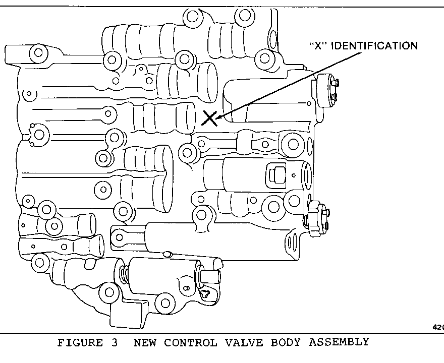
The new control valve body assembly is for the burned 3-4 clutch, and the high 2-3 shifts which are experienced on the C, K, and G, trucks gas/diesel applications only. The new control valve body assembly is identified with an "X" on the casting (see Figure 3) to distinguish it from the past control valve body assembly.
Only the new control valve body assembly is available for service. Refer to the parts manual for correct part numbers and model applications.
General Motors bulletins are intended for use by professional technicians, not a "do-it-yourselfer". They are written to inform those technicians of conditions that may occur on some vehicles, or to provide information that could assist in the proper service of a vehicle. Properly trained technicians have the equipment, tools, safety instructions and know-how to do a job properly and safely. If a condition is described, do not assume that the bulletin applies to your vehicle, or that your vehicle will have that condition. See a General Motors dealer servicing your brand of General Motors vehicle for information on whether your vehicle may benefit from the information.
