EATON LIMITED SLIP REAR AXLE DIAGNOSIS AND REPAIR

EATON LIMITED-SLIP REAR AXLE 1984 FIREBIRD
A limited-slip axle manufactured by Eaton was used on 1984 Firebirds built during the later part of the model year. The following information covers only items which are different than the standard axle. For all information not included here, refer to Section 4B of the 1984 Firebird Service Manual.
CONTENTS
General Description ............1 Assembly .................6 Diagnosis.........................2 Torque Specifications ....7 Checking Differential Operation.2 Special Tools ............8 Unit Repair ......................4 Axle Specifications ......8 Disassembly ....................4
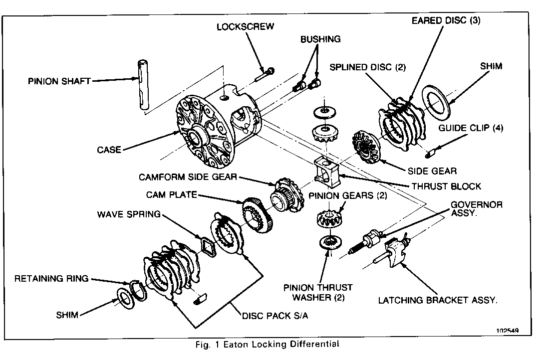
The Eaton Locking Rear Differential allows for normal differential function, as noted in the Standard Rear Axle section. Typical construction is shown in Figure 1. In addition, the Locking Rear Differential incorporates multi-disc clutch packs and a speed sensitive engagement mechanism, which locks both wheels together if either wheel should spin excessively during slow vehicle operation.
Under light loads, the clutch plates alone tend to lock axle shafts to the differential case, and therefore, each other. This is due primarily to the gear separating load developed on the RH clutch pack. This induced clutch torque capacity resists motion between the side gear and the rear axle differential case. The axle shaft torques developed when turning a corner will overcome this capacity and allow differentiation. Also, heavier throttle application will cause differentiation, but this initiates the full-lock feature of the unit.
Full locking is accomplished through the use of a flyweight governor mechanism, cam system, and multi-disc clutch packs. The flyweights on the governor mechanism move outward to engage a latching bracket whenever the wheel-to wheel speed varies by approximately 100 rpm or more. This action retards a cam which, in turn, compresses the multi-disc clutch packs locking both side gears to the case. The 100 rpm wheel-to-wheel speed allows for cornering without differential lock-up.
At vehicle speeds above approximately 20 mph (32 km/h), the latching bracket overcomes a spring preload and swings away from the flyweights. At this vehicle speed or greater, the differential will not lock, as the added traction is generally not required.
All rear axle parts of vehicles equipped with the Locking Rear Axle are interchangeable with those equipped with the conventional rear axle, except for the case assembly.
DIAGNOSIS
Checking Eaton Locking Differential Operation
1. Place the vehicle on a frame-contact hoist, allowing free rotation of the rear wheels.
2. Raise hoist until wheels clear floor. Holding one wheel stationary, slowly rotate other wheel approximately 1/2 revolution persecond, in both the forward and reverse directions. Wheel should rotate freely. If both wheels attempt to turn togehter, the differential is locking and is defective.
3. Raise hoist to maximum height with one person in vehicle.
4. Start engine making sure that carburetor is set correct slow idle speed.
5. With automatic transmission, apply parking brake, then place transmission in drive. With manual transmission, depress clutch and place transmission in first gear.
6. Have an assistant lock one rear wheel by pulling one parking brake cable from under the vehicle.
7. With engine at low idle, slowly release brakes or slowly engage clutch, as required.
8. Locked rear wheel will remain stationary and free wheel will begin turning. It is important that brakes or clutch be released slowly enough to start the free wheel turning and allow the free wheel to gradually increase in speed. As speed of the free wheel is increased, the differential will lock causing the rotating wheel to wtop or both wheels to turn at the same speed. The engine may stall if equipped with a manual transmission. It may be necessary to accelerate engine until approximately 10 mph is indicated on vehicle speedometer to cause differential lock. If indicated speed can be increased beyond 20 mph (3 2 km/h) without causing differential lock, the unit is not functioning properly. Rapid release of brakes or clutch, or rapid acceleration of engine will invalidate test.
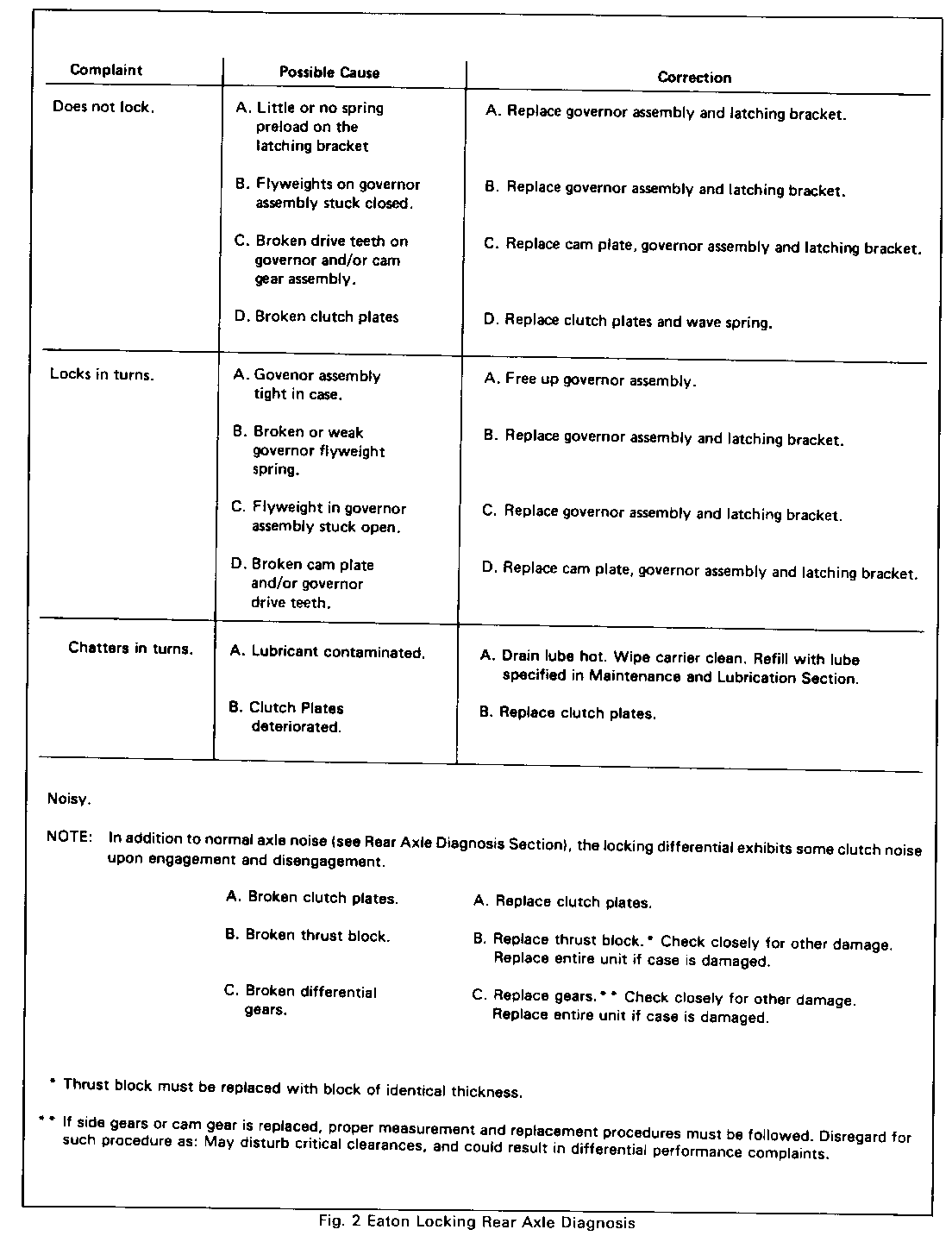
9. Lock opposite rear wheel and repeat procedure. The following chart provides guidelines for diagnosis and repair of differential complaints.
Complaint Possible Cause Correction ---------- -------------- ---------- Does not lock. A. Little or no spring A. Replace governor assembly preload on the and latching bracket. latching bracket
B. Flyweights on governor B. Replace governor assembly assembly stuck closed. and latching bracket.
C. Broken drive teeth on C. Replace cam plate, governor governor and/or cam assembly and latching gear assembly. bracket.
D. Broken clutch plates D. Replace clutch plates and wave spring. Locks in turns. A. Govenor assembly A. Free up governor assembly. tight in case.
B. Broken or weak B. Replace governor assembly governor flyweight and latching bracket. spring.
C. Flyweight in governor C. Replace governor assembly usembly stuck open. and latching bracket.
D. Broken cam plate D. Replace cam plate, governor and/or governor assembly and latching driveteeth. bracket.
Chatters in turns. A. Lubricant contaminated. A. Drain lube hot. Wipe carrier clean. Refill with lube specified in Maintenance and Lubrication Section. B. Clutch Plates B. Replace clutch plates. deteriorated.
Noisy.
NOTE: In addition to normal axle noise (see Rear Axle Diagnosis Section), the locking differential exhibits some clutch noise upon engagement and disengagement.
A. Broken clutch plates. A. Replace clutch plates.
B. Broken thrust block. B. Replace thrust block. * Check closely for other damage. Replace entire unit if case is damaged. C. Broken differential C. Replace gears. **Check closely for gears. other damage. Replace entire unit if case is damaged.
*Thrust block must be replaced with block of identical thickness.
** If side gears or cam gear is replaced, proper measurement and replacement procedures must be followed. Disregard for such procedure as: May disturb critical clearances, and could result in differential performance complaints.
Figure 2
Due to critical internal clearance dimensions, the differential case cannot be serviced separately. If any case damage is found, the entire differential must be replaced. Internal clearances are such that shims, reaction block, and gears, should not be replaced unneccessarily even if slight wear indications are present. If shims, reaction block, or gears must be replaced due to damage, correct measurement and replacement procedures must be followed. Failure to do so may disturb critical clearances and could result in differential complaints.
Internal components can be inspected through the windows of the diffenential housing.
If the governor assembly and latching bracket are the only items to be replaced, proceed only through step No. 2 of the disassembly procedure. To install new governor and latching bracket, begin at step No. 6 of the reassembly procedure.
Disassemble
Case
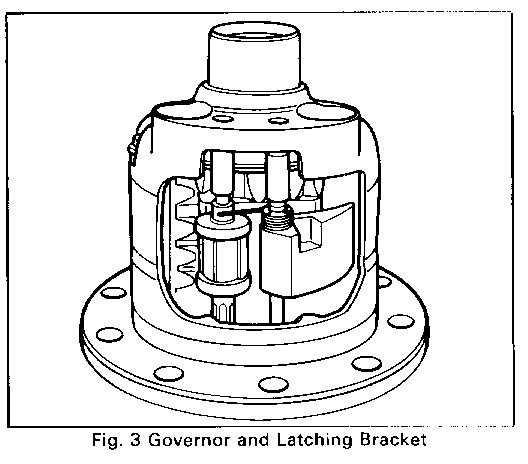
1. Note position of governor and latching bracket assembly, Figure 3. Remove ring gear and side bearings following procedures established for the standard differential.
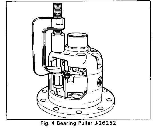
2. Using bushing puller tool J-26252, remove governor assembly and latching bracket by pulling the retaining bushings as shown in Figure 4. Pull the latching bracket spring out of the way while pulling the governor assembly bushing to prevent damage.
3. Remove lock screw and pinion shaft, and roll out differential pinion gears and pinion thrust washers. Discard lock screw.
4. Remove thrust block.
5. Remove cam gear, disc pack assembly and shim.
6. Remove R.H. disc pack assembly and shim.
Clean
All parts with solvent. Inspect all bearing for chipping or evidence of excessive wear. Replace parts as needed.
Inspect
All differential components for excessive wear and breakage. Replace parts as needed. The following are serviceable components for this differential:
-Governor assembly and latching bracket with spring.
-Cam plate
-Clutch disc pack with guide clips (Both LH and RH)
-Pinion cross-shaft
-Pinion gears, side gear and camgear
-Pinion thrust washers
-Reaction block (8 sizes)
-Retaining ring
-Flange end shim (8 sizes), Bell end shim (8 sizes)
-Governor Bushing
-Disc Guide Clips (Both LH and RH)
If only the reaction block or flange end shim must be replaced, the original pieces must be carefully measured for thickness and replaced with a piece of the same size.
Cam/Clutch Service ------------------ Disassemble -----------
Flange End
If cam plate or clutch discs must be replaced, the cam gear sub-assembly must be serviced as follows:
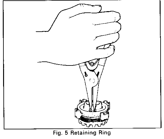
1. Remove retaining ring (use .06 external snap ring pliers). Refer to Figure 5.
2. Remove discs and camplate. Keep all components in the proper order.
Assemble
Flange End
Replace cam plate and wave spring or clutch discs as necessary and reassemble as follows. Refer to Figure 1.
1. Place gear on bench with hub end up.
2. Cam plate with cam form down to mate with cam form on gear.
3. On to cam plate: (2) eared discs, (1) splined disc, and (1) wave spring alternately as shown.
4. On to gear hub (2) splined discs and (3) eared discs alternately as shown. Begin and end with an eared disc.
5. Install retaining ring.
Disassemble
R.H. Clutch Pack ---------------- 1. Remove dise pack and shim from side gear. Keep discs in order.
Assemble
R.H. Clutch Pack ----------------
1. Replace discs and/or clips, as required.
2. Material on gear hub (two splined discs and three eared discs) alternately as shown in Figure 1. Maintain original sequence, if new discs are not used. Reinstall original shim, or a new shim with original thickness.
If gear hubs are scored, rough or show abnormal wear, check condition of bores in case. If they are damaged or oversize, the entire unit must be replaced.
Pinion Gears
Replacement
If it is necessary to replace the pinion gears due to pitting of the teeth scoring of the pinion shaft bearing surface, or breakage, it will be necessary to disassemble the unit following Steps 1 through 3 under case disassembly. Install new pinion gears and pinion thrust washers, and reassemble unit as described in Steps 4 through 9 of case reassembly.
If camgear, side gear, or pinion gears are broken, check for other damage and replace parts as needed. If case is damaged, the entire unit must be replaced.
Camgear (L.H. Side Gear) ------- Replacement ----------- If it is necessary to replace the camgear due to pitting of the teeth, scoring of the hub, or breakage, it will be necessary to disassemble the unit completely as described in Steps 1 through 6 of case disassembly and in Steps 1 through 2 of cam/clutch service. When replacing the camgear, it will be necessary to adjust (by selecting the correct shim) the camgear to pinion gear backlash using the following procedure:
1. Install the new camgear and disc pack sub assembly, using the original shim, into the flang end of the case. Place pinion gears and pinion thrust washers into their respective locations in the case, manually depress the camgear into its bore and slide the pinion shaft through the case and both pinion gears. If installation of the pinion shaft is prevented by the pinion gears, it will be necessary to replace the original shim with one of less thicnkess.
2. Once the pinion shaft is installed, with lockscrew in place, index one tooth of the pinion gear nearest the pinion shaft lockscrew so that it points downward, perpendicular to the case flange. Use a large tapered screwdriver or similar shaped tool and firmly wedge it between the camgear and pinion shaft.
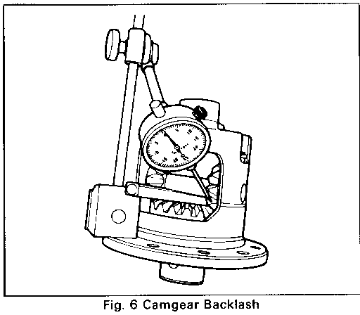
3. Using a dial indicator mounted to the case flange Figure 6, check pinion to camgear backlash by pulling the pinion gear firmly into its seat and rotate back and forth while reading the gage, note reading. Repeat the above procedure of indexing and checking backlash of the pinion gear opposite the pinion shaft lockscrew, and not reading. If backlash is not between .010 and .018, change shim size and repeat backlash procedure until the correct backlash is obtained. The thinner the shim used, the greater the backlash reading will be.
When camgear and/or side gear is replaced, thrust block replacement and clearance procedure must be followed during reassembly of the unit. Failure to do so may disturb critical clearances and could result in differential complaints.
Side Gear (R.H.) ---------------- Replacement ----------- If it is necessary to replace the R.H. side gear due to pitting of the teeth, scoring of the hub, or breakage, it will be necessary to disassemble the unit as described in Steps 1 through 6 of case disassembly. When replacing the side gear, it will be necessary to adjust (by selecting the correct shim) the side gear to pinion gear backlash using a similar procedure as described in the camgear replacement section. However, backlash for the side gear should be adjusted to within .002-.010, with R.H. side gear wedged against case.
Thrust Block
Replacement
If it is necessary to replace the thrust block only, replace it with a new one of identical thickness. If the thrust block is broken, check for other damage and replace parts as necessary. If case is damaged, replace the entire unit.
If camgear and/or side gear is replaced, it will be necessary to check the side gear spread dimension and adjust block clearance as follows:
1. Install camgear and disc pack with camgear shim into the flange end of the case.
2. Install side gear and disc pack with shim into the bell end of the case.
3. Install pinion shaft and a new lockscrew into case.
Firmly wedge a large tapered screwdriver or similar shaped tool between the pinion shaft and camgear. Wedge another tapered tool between the pinion shaft and side gear.
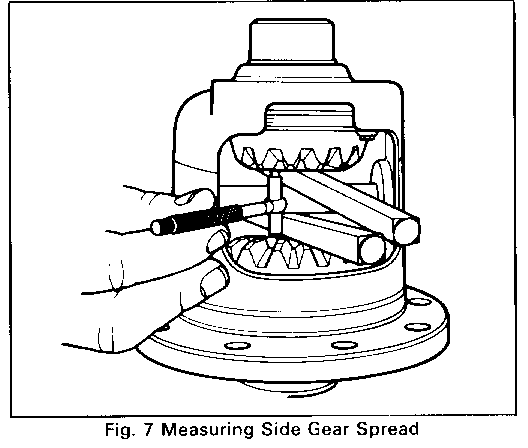
4. Using a 1" to 2" telescoping gage, measure the distance between the camgear face and side gear face (side gear spread). Make sure telescoping gage ends rest on the gear face, not on the gear teeth (Figure 7). Measure the telescoping gage with a 1" to 2" micrometer and note reading.
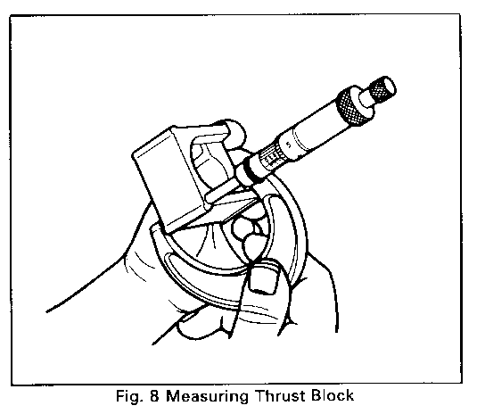
5. Measure the thickness of the original thrust block at outer corner, Figure 8, and note reading.
6. If the thrust block thickness is not within a range of .000 to .006 less than the side gear spread, adjust clearance with one of the following procedures:
a.) Reshim R.H. clutch disc pack. NOTE:Backlash of .002-.010 MUST still be maintained.
b.) Select a new thrust block of the correct size to obtain .000 to .006 clearance.
Case
Assemble
1. Install (4) clutch pack guide clips on the ears of the cam gear clutch pack using grease for retention.
2. Install cam gear assemby and original shim in flange end of case. If a new cam gear is installed, refer to differential gear replacement.
3. Lock an axle shaft in vise, in a vertical position. Mount the differential case over the end of the axle shaft engaging the spline of the side gear with the shaft. Assemble on to bell end gear hub (2) splined discs and (3) eared discs alternately as shown. Begin and end with and eared dis. Install (4) small clutch pack guide clips on the ears of the bell end clutch pack using grease for retention. Install in case with shim. If a new R.H. side gear is installed, refer to differential gear replacement. Install thrust washers onto back surface of pinion gears. Use a small amount of grease to adhere washers to gears.
4. Insert one pinion gear through the small window opening in the case while at the same time inserting the reaction block and other pinion gear ghrough the large window opening. Rotate the two pinion gears and thrust block 9 DEG so as to position the reaction block with the open side towards the small window opening in the case. Be sure the two pinion gears and thrust washers are in their proper location.
NOTICE: Thrust block thickness is critical to proper differential function. If new side gear or thrust block is installed, refer to thrust block or side gear replacement for adjustment procedures.
5. Install pinion shaft and a new lock screw.
6. Insert pinion governor assembly and latching bracket into case, Figure 3. Place straight end of latching bracket spring over and to the outside of the engagement shaft to preload the latching bracket against the governor assembly. Press bushing for governor assembly into case to give .004 to .020 shaft end play. A 3/8" diameter plug or socket will aid in pressing the bushings into the housing. Press latching bracket assembly bushing into the case to provide .000-.003 shaft end play. For the latching bracket, use bushing with the tapered hole. Ths bushing for the governor assembly has a straight hole.
7. Install ring gear and side bearings using the procedure outlined for standard differentials.
8. Place differential unit in carrier and adjust ring gear and pinion backlash and gear tooth pattern as outlined in the standard differential section.
9. Check axle operation as outlined in axle diagnosis.
NOTICE: Use only the rear axle lubricant recommended in Maintenance and Lubrication Section. The usage of any other lubricant or any additive may result in damage to the differential.
REAR AXLE SPECIFICATIONS
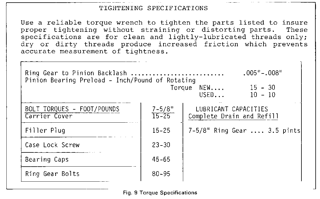
TIGHTENING SPECIFICATIONS
Use a reliable torque wrench to tighten the parts listed to insure proper tightening without straining or distorting parts. These specifications are for clean and lightly-lubricated threads only, dry or dirty threads produce increased friction which prevents accurate measurement of tightness.
Ring Gear to Pinion Backlash .......................... .005"-.008" Pinion Bearing Preload - Inch/Pound of Rotating Torque NEW.... 15 - 30 USED... 10 - 10
BOLT TORQUES - FOOT/POUNDS 7-5/8" LUBRICANT CAPACITIES --------------------------- ------ -------------------- Carrier Cover 15-25 Complete Drain and Refill
Filler Plug 15-25 7-5/8" Ring Gear .... 3.5 pints Case Lock Screw 23-30
Bearing Caps 45-65 Ring Gear Bolts 80-95
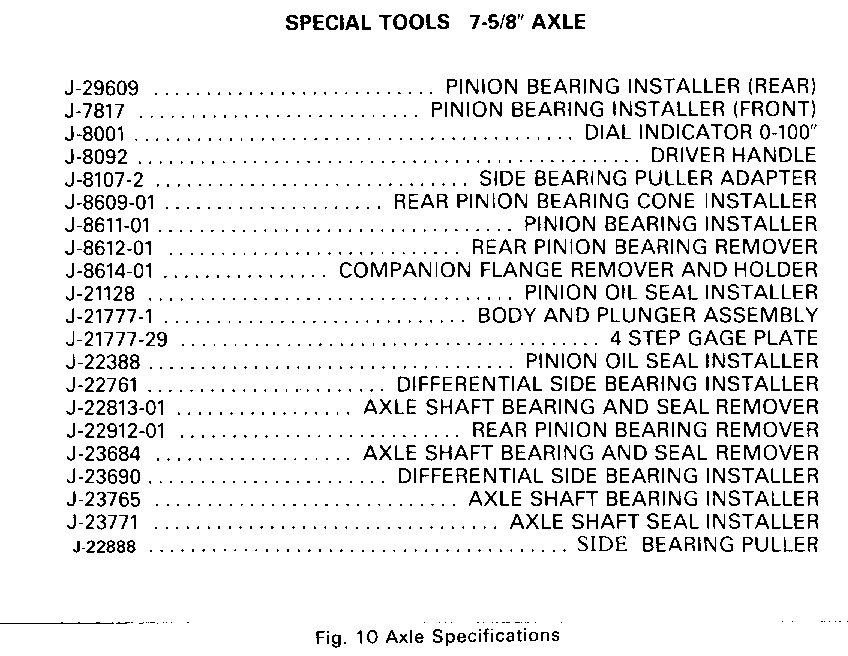
SPECIAL TOOLS 7-5/8" AXLE -------------------------
J-29609 . . . . . . . . ......... PINION BEARING INSTALLER (REAR) J-7817 . . . . . . . . . ........ PINION BEARING INSTALLER (FRONT) J-8001 . . . . . . . . . . . . . . . ........ . DIAL INDICATOR 0-100" J-8092 . . . . . . . . . . . . . . . . . . . ....... . . . DRIVER HANDLE J-8107-2.................................. SIDE BEARING PULLER ADAPTER J-8609-01 .. . . . .............REAR PINION BEARING CONE INSTALLER J-8611-01 . . . . . . . . ........ . PINION BEARING INSTALLER J-8612-01 . . . . . . . . . ........ REAR PINION BEARING REMOVER J-8614-01 .. . . ............. COMPANION FLANGE REMOVER AND HOLDER J-21128 . . . . . . . . ......... . . PINION OIL SEAL INSTALLER J-21777-1 . . . . . . . ......... . . BODY AND PLUNGER ASSEMBLY J-21777-29 . . . . . . . . . . ......... . . . . 4 STEP GAGE PLATE J-22388 . . . . . . . . . ........ . . PINION OIL SEAL INSTALLER J-22761 . . . . . .......... DIFFERENTIAL SIDE BEARING INSTALLER J-22813-01 . . ............... AXLE SHAFT BEARING AND SEAL REMOVER J-22912-01 . . . . . . ......... . . REAR PINION BEARING REMOVER J-23684 . . . ............... AXLE SHAFT BEARING AND SEAL REMOVER J-23690 . . . . . .......... DIFFERENTIAL SIDE BEARING INSTALLER J-23765 . . . . . . . ......... . . AXLE SHAFT BEARING INSTALLER J-23771 . . . . . . . ......... . . . AXLE SHAFT SEAL INSTALLER J-22888 . . . . . . . . . .......... . . . . .SIDE BEARING PULLER
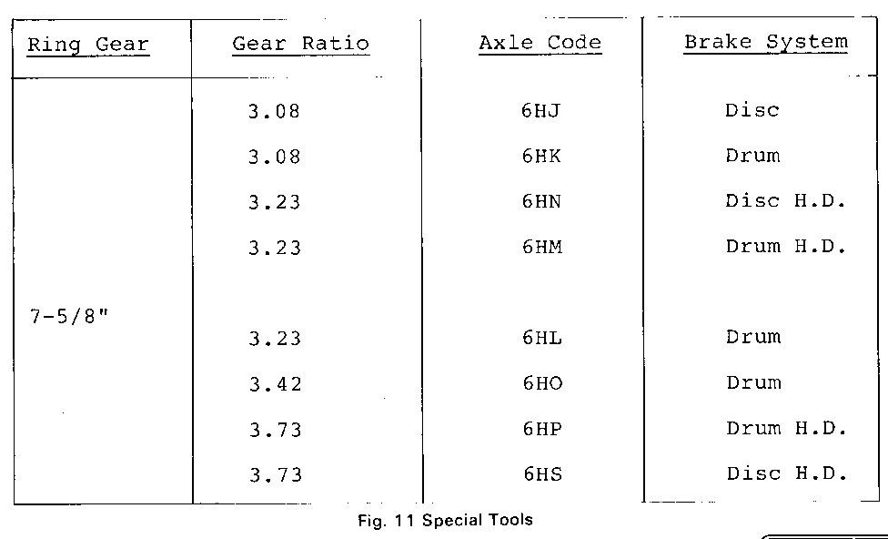
Ring Gear Gear Ratio Axle Code Brake System --------- ---------- --------- -------------
3.08 6HJ Disc
3.08 6HK Drum
3.23 6HN Disc H.D.
3.23 6HM Drum H.D.
7-5/8 " 3.23 6HL Drum
3.42 6HO Drum
3.73 6HP Drum H.D.
3.73 6HS Disc H.D.
General Motors bulletins are intended for use by professional technicians, not a "do-it-yourselfer". They are written to inform those technicians of conditions that may occur on some vehicles, or to provide information that could assist in the proper service of a vehicle. Properly trained technicians have the equipment, tools, safety instructions and know-how to do a job properly and safely. If a condition is described, do not assume that the bulletin applies to your vehicle, or that your vehicle will have that condition. See a General Motors dealer servicing your brand of General Motors vehicle for information on whether your vehicle may benefit from the information.
