QUARTZ INSTRUMENT CLUSTER DIAGNOSTICS AND WIRING DIAGRAM

VEHICLES AFFECTED: 1986 Firebird
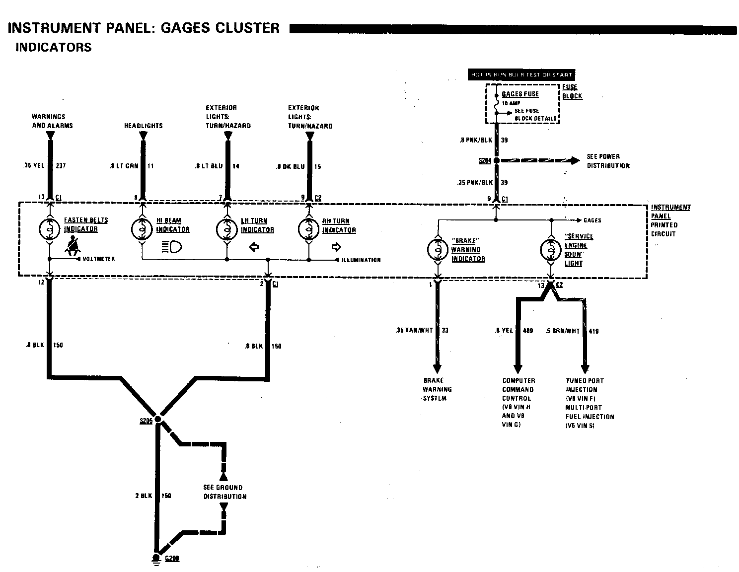
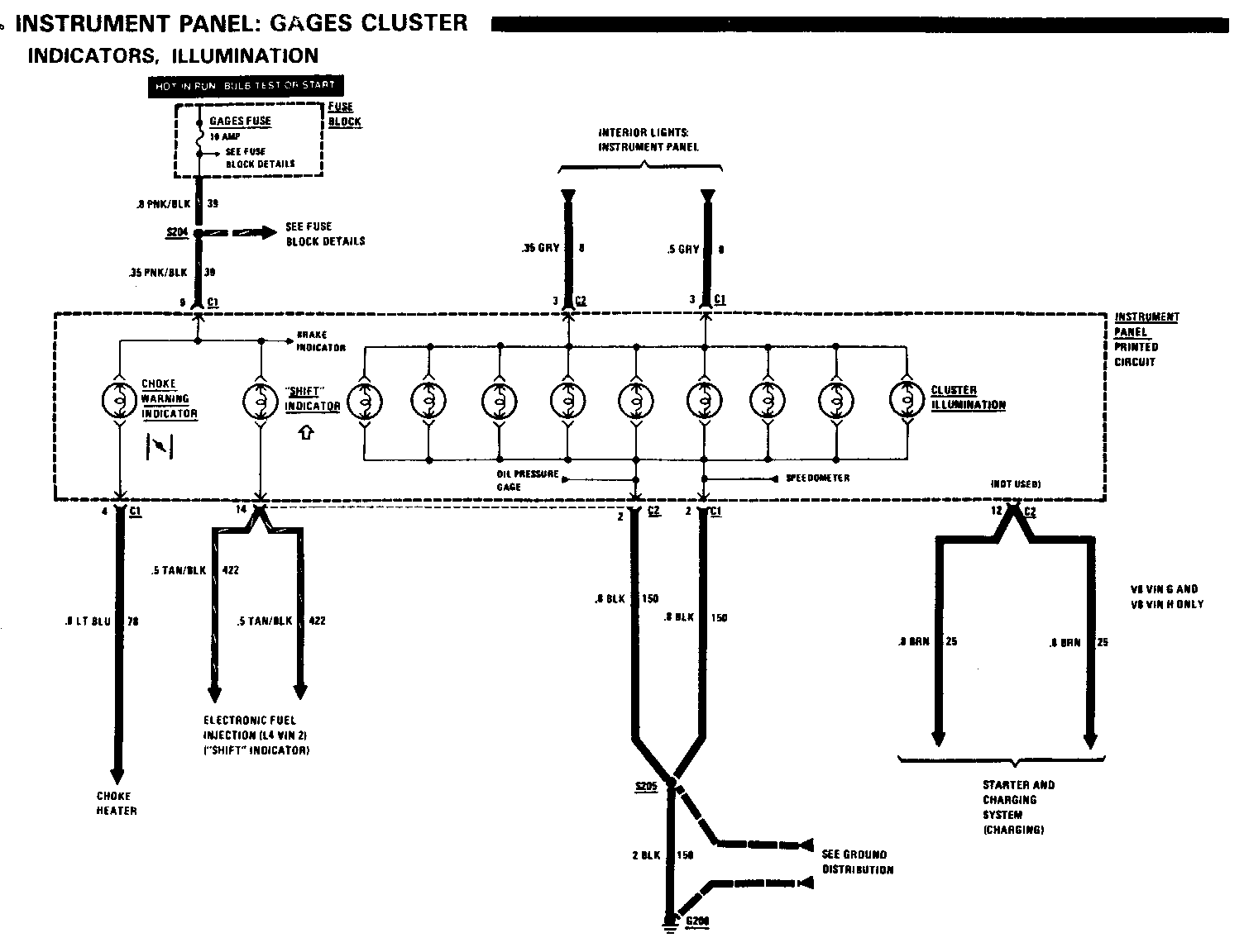
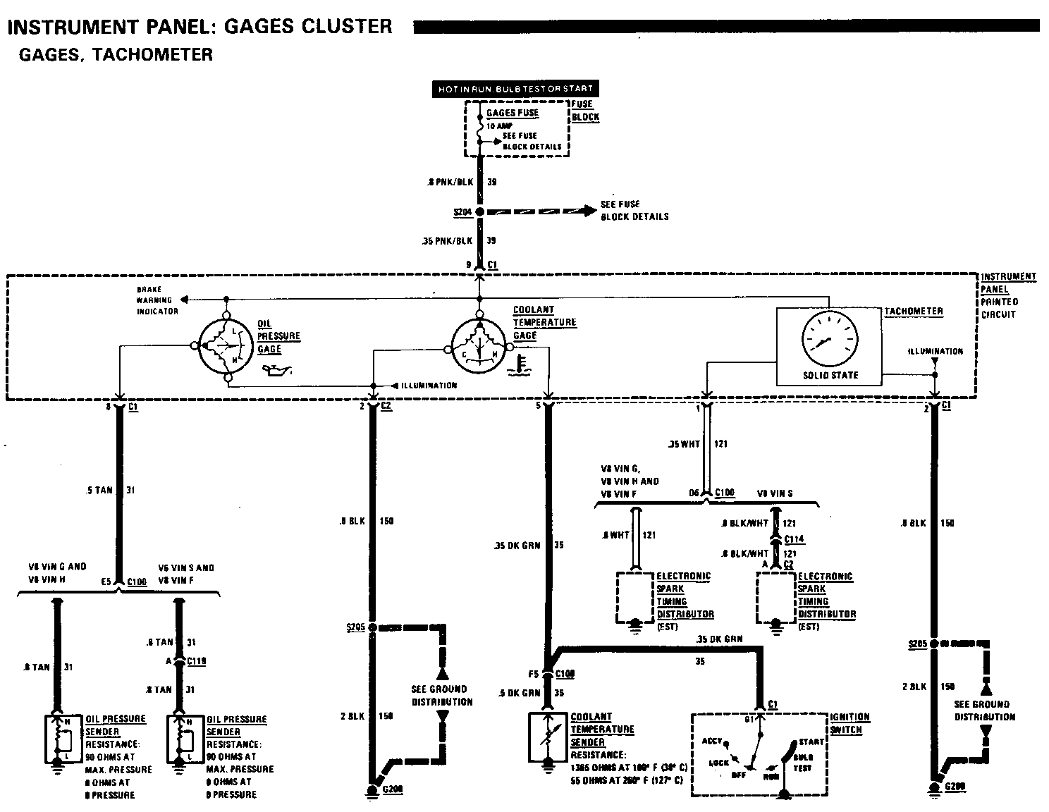
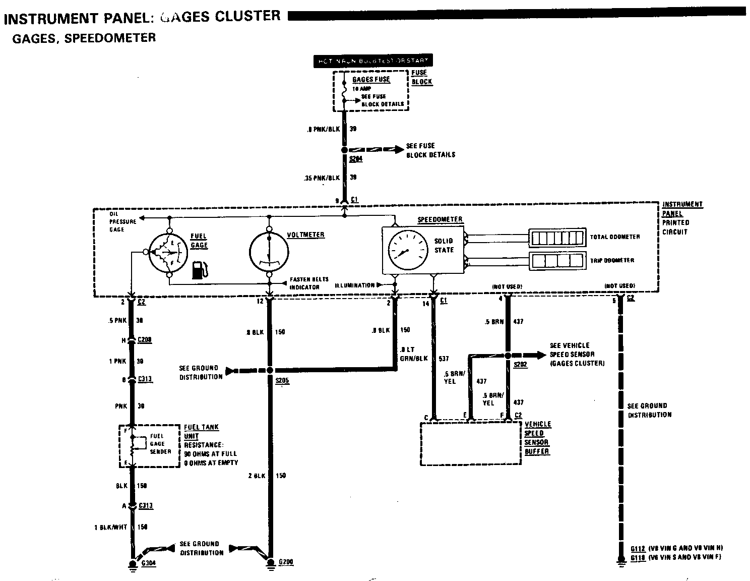
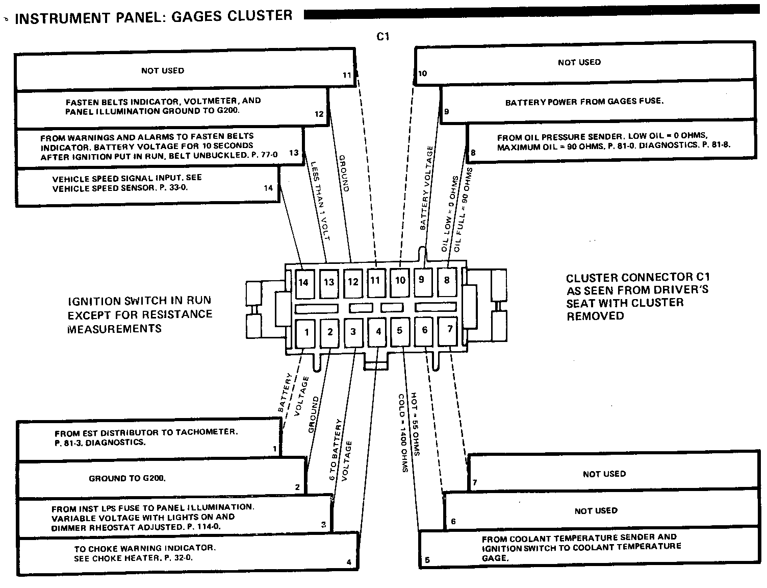
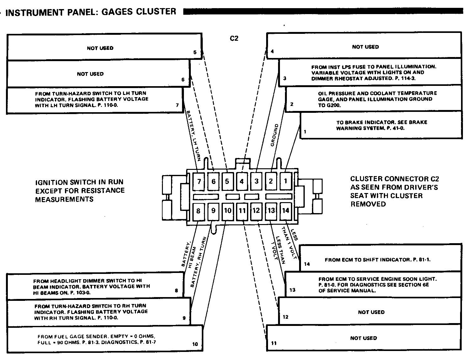
Some Firebird models use a quartz cluster. To aid in the diagnosis of this item, find attached schematics. Due to the late release of this part, it does not appear in the 1986 Firebird Preliminary Service Manual. It will be published as part of the final Service Manual.
INSTRUMENT PANEL: GAGES CLUSTER -------------------------------
SYSTEM CHECK
Indicators
The FASTEN BELTS, BRAKE, and CHOKE WARNING Indicators are on when the Ignition Switch is in START, RUN, or BULB TEST. These Indicators should go out when engine starts. Gages
The fuel gage, oil pressure gage, coolant temperature gage, and voltmeter should operate when the Ignition Switch is in START, RUN, or BULB TEST and also while the car is running.
TROUBLE SHOOTING HINTS
1. Check GAGES Fuse for all Indicators and Gages.
2. If the Fuel Gage does not operate, check that ground G304 is clean and tight.
3. If more than one indicator is out, inspect the printed circuit for cracks or flaws when replacing bulbs.
SYSTEM DIAGNOSIS
Pin-Out Tables
The tables on the following pages give the voltages or resistances you will find at connectors Cl and C2 with the cluster removed.
Measure all voltages to ground with the Ignition Switch in RUN.
Measure all resistances to ground with the Ignition Switch OFF and the nega- tive Battery cable disconnected.
COMPONENT LOCATION
Coolant Temperature Sender (VIN F) Lower LH side of engine 201-8-B Coolant Temperature Sender (VIN F) Lower LH side of engine 201-8-B Coolant Temperature Sender (VIN H) (VIN G) Lower LH side of engine 201-12-A Coolant Temperature Sender (VIN S) Top L/H front of engine, 201-2-B behind compressor Electronic Spark Timing (EST) Distributor (VIN F) Top rear of engine 201-8-C Electronic Spark Timing (EST) Distributor (VIN H) (VIN G) Top rear of engine 201-11-A Electronic Spark Timing (EST) Distributor (VIN S) Top rear of engine 201-5-B Fuel Tank Unit Top center of fuel tank Fuse Block Behind LH side of I/P, 201-15-A below light switch Ignition Switch Behind I/P, on top upper 201-16-A side of steering column Oil Pressure Sender(VIN F) Top rear of engine,near distributor 201-8-C Oil Pressure Sender (VIN H) Top rear of intake manifold 201-10-B (VIN G) Oil Pressure Sender (VIN S) Lower L/H side of engine 201-4-A Vehicle Speed Sensor Buffer Behind RH side I/P, near ECM 201-17-A C1OO (46 cavities) LH front of dash, left of 201-1-F brake master cylinder C208 (15 cavities) LH shroud, ahead of center 201-16-C access hole C313 (3 cavities) LH rear of car, under trunk, 201-22-A on frame rail G112 Rear of RH cylinder head 201-10-C G118 (VIN F) Rear of RH cylinder head 201-6-A G118 (VIN S) Rear of LH cylinder head 201-2-E G200 Behind I/P, left of steering column 201-15-A G304 Under rear seat, on support bracket 201-22-A S202 I/P harness, behind RH sidse of I/P 201-17-A S204 I/P harness, behind RH side of instrument cluster 201-15-A S205 I/P harness, behind RH side of instrument cluster 201-15-A
Check all ground terminals with a self-powered test lamp before making volt- age or resistance measurements.
INSTRUMENT PANEL: GAGES CLUSTER -------------------------------
Speedometer and Odometers Diagnosis
1. If the Speedometer and both Odometers do not operate, check for a speed signal coming from the Vehicle Speed Sensor Buffer, terminal C of connector C2 on the Buffer. See page 33-0. Vehicle Speed Sensor.
- If the speed signal is present, check the LT GRN/BIK wire to the Instrument Panel for an open. Also, check the printed circuit for a crack or flaw.
- If the wire and printed circuit are good. remove the Speedometer, Odometers, and the circuit board connected to them for exchange and repair.
- If the speed signal is not present, troubleshoot the Vehicle Speed Sensor circuit as described in Step 3.
2. If the Speedometer or either of the Odometers do operate, but the others do not operate, remove the Speedometer, Odometers and their circuit board for exchange and repair.
3. If the Speedometer reads "O" all the time, remove both connectors from the Vehicle Speed Buffer. Plug both of these connectors into connector J-33431-8 of I/P tester J-33431. With the tester set to ON, 54 mph, and 60 HZ and the Ignition Switch in RUN, the Speedometer should read 54 mph +/- 2 mph.
If the Speedometer reads correctly, the fault is in the Vehicle Speed Sensor (VSS) circuit. See page 33-0 for further diagnostics.
If the Speedometer reads incorrectly, disconnect the I/P tester and turn the Ignition Switch to RUN. Measure the voltage between terminal C (LT GRN/ BLK) of Buffer connector C2 and ground.
- If Battery voltage is present, replace the Speedometer Unit.
- If Battery voltage is not present, check the LT GRN/BLK wire between the Buffer and the Instrument Panel. Also check the printed circuit for cracks or flaws. Replace the Speedometer Unit if the wire and printed circuit are good.
4. If the Speedometer indicates vehicle speed but not the correct speed, check for:
correct tire inflation.
correct tire size.
correct Speedometer driven gears (see Section 7 of the Chassis Service Manual).
If these are correct, perform the electrical diagnosis in Step 3.
Tachometer Diagnosis
1. If the Tachometer does not operate. disconnect the Tachometer connector at the Electronic Spark Timing (EST) Distributor. Connect the mating cable from the J-33431 tester to the connector just removed. Plug in the tester and set switches to ON, and 54 mph. With the Ignition Switch in RUN:
The Tachometer should read:
- 8 cylinder - 900 R PM - 6 cylinder - 1350 R PM - 4 cylinder - 1800 RPM
If the Tachometer does not indicate cor rectly, disconnect the I/P tester and reconnect the EST Distributor. Measure the voltage at Instrument Panel connector C 1, terminal I (WHT) with the Ignition Switch in RUN (engine not running).
- If the voltage is above 10 volts, check the printed circuit for cracks or flaws. Replace the Tachometer if the printed circuit is good.
- If the voltage is below 10 volts, check the WHT wire to the Electronic Spark Timing (EST) Distributor.
If the Tachometer indicates correctly. the cause is an intermittent or bad connection. Check all connections and wiring.
Fuel Gage Diagnosis
1. If the Fuel Gage shows E when there is fuel in the tank, the sender circuit may be shorted. Open the inline connector C313 near the Fuel Tank Unit.
If the gage now reads F, the wiring is good. Install a new Fuel Tank Unit.
INSTRUMENT PANEL: GAGES CLUSTER -------------------------------
If the gage still reads E, check for a short in the PNK (30) wire between the fuel tank and the Instrument Panel. If the wire is not shorted and the printed circuit is good, replace the Fuel Gage.
2. If the Fuel Gage shows F when the tank is not full, open connector C313 and connect together terminals A (BLK) and B (PNK) of the harness half. Use a fused jumper.
If the Fuel Gage now reads E, the wiring is good. Install a new Fuel Tank Unit.
If the gage shows F, check for an open in either the PNK (30) wire to the Instrument Panel, or the BLK (150) wire to ground G304. If these wires are good and the printed circuit is good, replace the Fuel Gage.
3. If the Fuel Gage is not accurate, open connector C313 and connect the two red clip leads of tester J-33431 to terminals A (B LK) and B (PNK) of the harness half of C313. Set the resistance dials of the tester to 0 ohms and then to 90 ohms. The Fuel Gage should read E and then F.
If the gage responds correctly, install a new Fuel Tank Unit.
If the gage does not respond correctly, check the PNK (30) wire, BLK (150) wire and printed circuit. Replace the Fuel Gage if these wires are good.
Oil Pressure Gage Diagnosis
1. If the Oil Pressure Gage shows low after the engine has started, first check the oil pres sure with a manual gage. If the pressure is correct, continue with the electrical diagnosis.
Remove the connector from the Oil Pressure Sender.
If the gage now shows high pressure, the wiring is good. Install a new Oil Pressure Sender.
If the gage remains low, check for a short in the TAN (31) wire between the sender and the Instrument Panel. If this wire is not shorted to ground, and the printed circuit is good, replace the Oil Pressure Gage.
2. If the Oil Pressure Gage shows high before the engine is started, the sender circuit may be open. Remove the connector from the Oil Pressure Sender and short the TA N wire to ground.
If the gage now reads low, the wiring is good. Install a new Oil Pressure Sender.
If the gage remains high, check for an open in theTAN (31) wire back to the Instrument Panel. If the wire is good and the printed circuit is good, replace the Oil Pressure Gage.
3. If the Oil Pressure Gage is not accurate, remove the connector from the Oil Pressure Sender and connect one red clip lead from the J-33431 tester to the TAN wire terminal. Connect the other red clip lead to ground. Set the resistance dials of the sender to 0 ohms and then to 90 ohms. The gage should read low pressure and then show high pressure.
If the gage is correct, install a new Oil Pressure Sender.
If the gage is not correct, check the TAN (31) wire and printed cirucit. If they are good, install a new Oil Pressure Gage.
Coolant Temperature Gage Diagnosis
1. If the Coolant Temperature Gage shows hot when the engine is cold, the sender circuit may be shorted. Remove the connector from the Coolant Temperature Sender.
If the gage now shows cold, the wiring is good. Install a new Coolant Tem- perature Sender.
If the Coolant Temperature Gage remains hot, check for a short to ground in the DK GRN (35) wire between the sender and the Instrument Panel. Also. check the printed circuit for a short. If the wire and printed circuit are good,replace the Coolant Temperature Gage.
2. If the Coolant Temperature Gage shows cold when the engine is hot or warm, the sender circuit may be open. Remove the connector from the Coolant Temperature Sender and connect the terminal (DK GRN) of the harness connector to ground.
If the display now reads hot,the wiring is good. Install a new Coolant Temperature Sender.
If the display remains at cold, check for an open in the DK GRN (35) wire back to the Instrument Panel. If the wiring is good, and the printed circuit is good, replace the Coolant Temperature Gage.
INSTRUMENT PANEL: GAGES CLUSTER --------------------------------
3. If the Coolant Temperature Gage is not accurate, remove the connector from the Coolant Temperature Sender. Connect one red clip lead of the J-33431 tester to the harness connector terminal (DK G RN), and the other red clip lead to ground, Adjust the resistance dials of the tester to 1400 ohms and then to 55 ohms. The Coolant Temperature Gage should show low tem- perature, and then hot.
If the gage reads correctly, the wiring and the gage are good. Install a new Coolant Temperature Sender.
If the gage is not correct, check the DK GRN (35) wire and printed circuit. If these are good, install a new Coolant Temperature Gage,
Voltmeter Diagnosis
1. If the Voltmeter is not working properly, compare Voltmeter reading with the Battery voltage. If the gage is not correct, remove the Instrument Panel. Check the power and ground of the Voltmeter by connecting a test lamp between terminals 9 (PNK/BLK) and 12 (BLK) of the Instrument Panel connector C 1. With the Ignition Switch in RUN, the lamp should light.
- If the lamp lights, check the printed circuit for an open. Replace the Voltmeter if the printed cirucit is good.
- If the lamp does not light, check the PNK/BLK and BLK wires for an open.
CIRCUIT OPERATION
The operation of an individual indicator is described along with its circuit. Refer to the schematic and text for the circuit that is indicated below each of the indicators.
Tachometer
The Tachometer displays engine speed in rpm. Voltage pulses are taken from the ignition System and sent to the Tachometer. Solid State circuits process these pulses into a signal that drives the pointer of the meter. The Tachometer responds to the frequency of the voltage pulses (the number of pulses in a second). This increases with engine speed. A Tachometer Filter can be added to the circuit to round off the pulses and remove any spikes.
Fuel Gage
The pointer of the Fuel Gage is moved by the magnetic fields of two coils. The coils are at right angles each other. Battery Voltage is applied to the E coil and the circuit divides at the opposite end of the coil. One path con- tinues to ground through the F coil. Another goes to ground through the variable resistor of the Fuel Gage Sender.
When the tank is low, the resistance of the sender is low. A large flow of current passes through the E coil and the Fuel Gage Sender resistor. This moves the pointer towards E on the scale. When the tank is full, the sender resistance is high. More current now flows through the F coil, moving the pointer toward F on the scale.
With two coils operating the pointer, the gage is not af fected by changes in the system's Battery voltage.
Oil Pressure Gage
The engine oil pressure is displayed by the Oil Pressure Gage. The pointer of the gage is moved by two coils, and its operation is similar to that of the Fuel Gage.
The Oil Pressure Sender is connected to the junction of the two coils. It has low resistance when the oil pressure is low, and 90 ohms resistance when the oil pressure is high. This changing resistance changes the current flow through the coils. The magnetic fields of the coils move the pointer from low to high.
Coolant Temperature Gage
The Coolant Temperature Gage is also operated by two coils. Battery voltage is applied to both coils. One is grounded directly and the other is grounded through the Coolant Temperature Sender. This has 55 ohms resistance at 260 DEG F (hot coolant) and its resistance becomes greater at lower temperatures. It is approximately 1400 ohms at 100 DEG F. This causes the current through the sender and one coil to increase as the coolant temperature increases. This moves the pointer.
Speedometer and Odometers
The Speedometer is operated by an electronic circuit. The Vehicle Speed Sensor (VSS), located in the transmission, generates an AC voltage whose frequency is proportional to the speed of the vehicle. This goes to the Vehicle Speed Buffer and then to the Speedometer circuit board in the Instrument Panel. The solid state circuit drives the pointer of the Speedometer. There is no speedometer cable in the vehicle.
The same speed signal from the Vehicle Speed Buffer is processed by the Speedometer circuit board to drive the Odometers. They are operated by a motor that responds to pulses from the Speedometer circuit.
Voltmeter
The Voltmeter measures the electrical system voltage with the Ignition Switch in RUN, BULB TEST, or START. With the engine stopped, the Voltmeter indicates Battery conditions. With the engine running, the Voltmeter indicates Charging System operation.
General Motors bulletins are intended for use by professional technicians, not a "do-it-yourselfer". They are written to inform those technicians of conditions that may occur on some vehicles, or to provide information that could assist in the proper service of a vehicle. Properly trained technicians have the equipment, tools, safety instructions and know-how to do a job properly and safely. If a condition is described, do not assume that the bulletin applies to your vehicle, or that your vehicle will have that condition. See a General Motors dealer servicing your brand of General Motors vehicle for information on whether your vehicle may benefit from the information.
